By Mike Bunning, Softing
When we think of fiber-optic networks, most of us picture thin, arcing pathways of light tracing a web of instantaneous telecommunications around the world. When we think of server farms or data centers, we imagine thick bundles of twisted-pair cable nestled in cable tray and spraying a rainbow of wires into racks of blinking equipment.
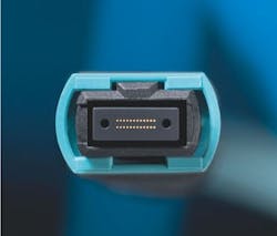
So far, so good. Except these days, more and more fiber being installed into the backs of that equipment, thanks to multiple-fiber cables terminated with MPO connectors.
It is hard to see exactly where the future lies in terms of fiber-versus-copper for the 40/100G data center buildout. The present seems to be a case of co-evolution, as growth in the demand for bandwidth and transmission density spurs innovation to supply the necessary solutions that one or the other has lacked. Design constraints include the requirement of low power consumption and the steep price of real estate for the network physical plant. The MPO (multi-fiber push-on) design is a perfect example of the kind of adaptive engineering that helps fiber-optic cable compete with copper in enterprise facilities and data centers. MPO connectors allow cable carrying multiple fiber strands to be terminated with a single push-on connection at patch panels or cassettes linking a multi-fiber trunk to fanout cables with standard SC/LC ends. Some SFP will now directly accept an MPO/MTP connector. This saves a ton of time in deployment. More importantly, installers can quickly field-test multi-fiber permanent links before and after they run, vouching for the integrity of the cable and installation.
Pinned design versatile, complex
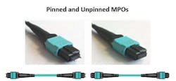
The most common MPO design standard calls for terminating up to 12 fibers in one row. A 2-pin mating system is used to perfectly align fiber ends for insertion into a coupler or adapter that joins another link terminated with an MPO connector and stabilizes the connection. Links and terminals are such that individual MPO connectors and couplers are either pinned or unpinned, i.e. male/female.
Moreover, MPO connectors are keyed for up or down orientation, allowing the order of fibers in the alignment to be reversed. In this manner, a multitude of cable/connector configurations are possible across a multi-link cable channel. Such variability gives designers a great deal of freedom, but it creates more opportunities for error in installation and certification. We will address this in a moment.
Loss budgets are hard
Signal loss can be looked at as a determining factor in the choices made when designing a cabled system. This is especially true as the need to certify high-bandwidth applications intensifies. Although the principle of signal loss is similar in optical fiber and copper twisted-pair, their physical properties are completely different.
Within the fiber realm, multimode fiber has emerged as a better choice for the shorter distances of cable trunks inside buildings where the superior bandwidth-distance product of singlemode fiber is essentially wasted. The much larger multimode core is optimized at lower wavelengths allowing less-expensive light sources, such as LEDs and VCSELs. While multimode is physically less efficient at containing light, the new encircled flux (EF) standard (IEC 61280-4-1) means single strand multimode fiber cable links can be certified with tighter loss budgets. EF provides a method for specifying light-fill limits in launch conditions during reference setting and testing. While not directly relevant to the MPO, the ability to certify EF compliance is no small thing, as loss-limit savings can sum over entire channels and lead to a more cost-effective 40G application.
Materials aside, there are technical factors that make loss budgets for the 40/100G fiber network hard to pin down in real installations. Simon Harrison, general manager of Softing’s WireXpert business, pointed out in a recent talk on multifiber testing that the standards governing Ethernet, cabling, and testing do not uniformly account for the various potential configurations that pinned MPO connectors introduce in multifiber links. In cases where the user must decide which limits to employ, it is possible for standards governing individual links to exceed the limit imposed by IEEE 802.3 equipment-to-equipment standard. In other words, while testing methods for individual links must comply with IEC 61280-4-1, the entire channel must conform to IEEE 802.3 for 40G performance to be guaranteed.
There is also the methodology factor. Network installations can fail certification just as easily from wrong or careless test methods as they can from faulty components. Because of its refractive and reflective qualities, glass fiber ends are carefully polished and tuned at the factory for minimal insertion loss. This is particularly the case with MPO connections, where so many fibers in such a small space must meet each other perfectly every time a connection is made. Without strict adherence to fiber-optic test practices, which include microscopic examination and proper equipment calibration and maintenance, the whole exercise of computing signal loss over multilink fiber channels becomes meaningless.
Taking test methods and gear up a notch
To sum up, there are two areas of additional complexity to navigate with the 40G fiber network: fuzzy loss budgets and MPO channel topology.
Multifiber trunks terminated with MPO connectors obviously take a lot less time to install and test than the single-strand equivalent. But certifying the 40G fiber data center can be tricky because both reference-setting and auto-setting must occur under the precise pinned/unpinned conditions for each installed permanent link, as well as for the complete equipment-to-equipment channel. This is easier said than done. Testers come either pinned or unpinned. A variety of test and reference cords in different pinned/unpinned configuration must be on hand to properly set reference and test conditions for each link and for the MPO channel. The technician must also be able to test links from the MPO aggregation endpoint to the various patch panel, cassette and equipment SC/LC interface connections. This requires another test unit and reference cords compatible with the non-MPO terminal.
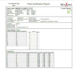
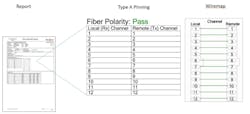
Here, it is worth noting that most test instrument manufacturers require separate devices for testing MPO. The WireXpert certifier from Softing employs a modular system of plug-in adapters designed for specific types of cable, so you only need the MPO adapter set (pinned). In fact, WireXpert is currently the only certifier that offers a modular solution for MPO. Modularity enables smart local and remote units, which comes in handy for testing MPO-to-SC/LC cassettes. Simply plug the MPO light source adapter into the remote unit and the standard multimode adapter into the local unit on the equipment end. The WireXpert MPO test report also includes an extremely helpful polarity map, clearly indicating the 1-1 Type A of 1-12 Type B cable.
Looking (and thinking) ahead
If you are a contractor migrating to fiber or looking ahead to an increase in fiber wire data center business you will need to look closely at your current testing device arsenal and deployment strategy. Going forward, there are distinct advantages to Softing’s WireXpert modular platform. It was designed from the start to be an updateable device with interchangeable adapters that support permanent link and channel certification for Category 5e/6/6A and now Category 8 copper, as well as singlemode, multimode (EF-compliant), and MPO/MTP fiber. This modular pedigree is the reason WireXpert is the only one with an adapter-set solution for MPO. It also explains why the device itself was engineered with so much headroom to begin with: WIreXpert tests up to 2.5 GHz—the highest available in a handheld device—and it is the only one that can do it. Combine all that with the Softing Dual Control System that pair smart-local and smart-remote units, and you have a certification system that is literally made for 40/100G Ethernet.
Mike Bunning is manager of business development at Softing.


