Wrap your mind around BIMMF testing
Mandrels, encircled flux and reference jumpers are some of the factors that make for a potentially confusing process.
By Derek Whitehurst, Corning Cable Systems
With their introduction in 2009, 50/125-µm bend-insensitive multimode fiber (BIMMF) products are becoming commonplace in the local area network (LAN) and data center application spaces. Multiple vendors have released BIMMF products, and some companies have switched their 50/125-µm offerings to exclusively bend-insensitive products. There has been significant and steady deployment of bend-insensitive fiber products over the last few years. Standards bodies within both the Telecommunications Industry Association (TIA; www.tiaonline.org) and the International Electrotechnical Commission (IEC; www.iec.ch) are actively working to incorporate improved macrobend performance to existing multimode fiber standards. Until then, BIMMF is commercially available. Some manufacturers' offerings already comply with existing IEC and TIA detailed fiber standards for OM2, OM3 and OM4.
Because BIMMF is still a relatively new product class, channel insertion loss test standards have not fully incorporated these improved versions of 50/125-µm fiber. Additionally, channel insertion loss test standards are changing with the adoption of encircled flux (EF). Because of this, installers need to understand whether or not they must modify their existing test method for BIMMF. This article will review how BIMMF affects testing, and what options are available to ensure that you are achieving optimal results.
Legacy source testing
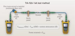
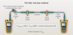
A system using BIMMF is compliant to existing IEC/TIA OM2, OM3 and OM4 standards and does not require a different testing method than a system using legacy 50/125-µm fibers. The only difference in the test setup would be if the tester was using BIMMF test (reference) jumpers. Although a new standard for testing is in place (TIA-526-14-B Optical Power Loss Measurement of Installed Multimode Fiber Cable Plant), the majority of installers are still using the testing methods specified in the previous standard (TIA-526-14-A). Because of this, we will review BIMMF impacts for both the previous and the current testing standards during this time of transition in the industry. The typical end-to-end test setup consists of a source on one end with a reference jumper patching into the link being tested, and a power meter on the other end coupled into the link with a reference jumper.
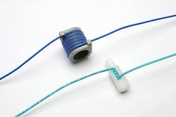
Previous multimode fiber testing standards that are still widely used today require the use of a mandrel to strip out the higher order modes of light. These higher order modes can negatively affect your testing accuracy if not adequately removed. For legacy 50/125-µm multimode fiber, wrapping the test reference jumper around a designated diameter mandrel five times is specified in TIA-568-C.0 Generic Telecommunications Cabling for Customer Premises, to achieve the desired launch condition. As the fiber bends around the mandrel, these higher-order modes of light are stripped out. Because BIMMF is designed to reduce bending losses, the specified mandrels may not produce a tight enough bend to induce the proper stripping of the higher order modes. For example, wrapping a BIMMF reference jumper around a 22-mm mandrel is essentially equivalent to not testing with a mandrel, and will yield inaccurate test results.
Another aspect that must be considered is the test wavelength used for system performance validation. Traditionally, standards have called out testing multimode fiber at both 850 and 1300 nm. BIMMF exhibits dramatically better bend performance at both wavelengths. However, most BIMMF designs are optimized to have the best bending performance at 850 nm, where the vast majority of 50/125-µm systems are operating. Because manufacturers have optimized the design for a preferred wavelength, BIMMF exhibits up to a 10x improvement in bending performance over legacy 50/125-µm designs at 850 nm and 4x improvement at 1300 nm. Because of this difference in bending performance, it is not guaranteed that one mandrel can achieve the same launch condition at both 850 and 1300 nm. Thus, installers need to look at how they test, and which options will work best with the 50/125-µm systems they are installing.
Testing standards are changing to allow more flexibility in specifying the wavelength that will ensure system compliance. Previously it was typical to have multimode systems running at 850 and 1300 nm, based on different transmission data rates, especially with 62.5/125-µm fiber. As 50/125-µm fiber has become the fiber of choice for new network builds, this has shifted, and transmission standards such as Ethernet and Fibre Channel use 850 nm, and only a limited set of older legacy products operate at 1300 nm. In fact, standards define OM3 and OM4 fiber types as being optimized to work at 850 nm. Therefore, the questions each installer has to ask are:
- What is the customer requirement?
- What is required to be standard-compliant?
- What is necessary to ensure system compliance?
ANSI/TIA-568-C.0 and ISO/IEC 11801 Generic Cabling for Customer Premises stipulate testing at both 850 and 1300 nm in the backbone cable, and 850 nm or 1300 nm for horizontal cabling. However, recent studies looking at the correlation between 850 and 1300 nm have allowed a modification in TIA-526-14B, where 850 or 1300 nm are acceptable for system validation in the backbone for legacy 50/125-µm systems. This was accomplished by adjustment of the 850 and 1300 nm EF limits to produce comparable losses.
The elimination of this bias provides an opportunity to ensure dual-wavelength compliance of a passive component or a short cable-plant link using a single source. This now allows an installer to test the system at the wavelength where it is expected to perform, which in all likelihood will be 850 nm. It is important to remember that this flexibility in testing is only applicable when using TIA-526-14B testing methods. Work is ongoing within standards bodies to determine if the same modification is applicable to BIMMF systems, but those recommendations are not available at this time. Customer requirements should always take precedence in any testing-requirements decision.
Now that we have an understanding of the wavelengths required for testing, we can turn our attention to achieving the correct launch condition. When testing a system using BIMMF, it is not required that the launch reference jumpers use BIMMF. What is required is generating the correct launch condition regardless of the test method. If the installer is using the previous standard to test, this can be accomplished through combining a reference jumper containing legacy 50/125-µm fiber with a specified mandrel from the previous standard, or with BIMMF reference jumpers and the use of a specially sized mandrel that can achieve the equivalent launch conditions. Because earlier testing standards did not incorporate BIMMF, these specially designed mandrels are not included in the previous standards. Nor are they referenced in current standards, where the launch condition is specified, but the means to achieve the launch is not.
If you are testing using the previous standard, you should always consult with your manufacturer of BIMMF products for their recommendation on mandrel size. A5 850 nm, using a 4-mm-diameter mandrel on BIMMF has been shown to yield a launch condition equivalent to that achieved using a 22-mm mandrel on a legacy fiber cable. At 1300 nm, a 22-mm-diameter mandrel is still acceptable for both legacy and BIMMF jumpers.
Two possible options are shown in the nearby table. The installer must think through the best approach for each situation. If you are required to test at both wavelengths for your particular application, you should always choose the legacy 50-µm reference jumper with a 22-mm mandrel at 850 and 1300 nm (listed as Option 1 in the table). In typical installations, you will attach the port of the link in question and measure both 850 and 1300 nm at the same time and move to the next port. It is easy to switch between wavelengths because you are using the same jumper with the same mandrel.
However, to do the same using a BIMMF reference jumper, you will have to test the system at one wavelength using the correct mandrel, then retest the system at the other wavelength using a different mandrel (listed as Option 2 in the table).
If you are testing your system at one wavelength (which most likely would be 850 nm), you could use either option with the same result and testing time.
Encircled flux source testing
With IEC-61280-4-1 Ed. 2.0 Fibre-optic Communication Subsystem Test Procedures – Part 4-1: Installed Cable Plant – Multimode Attenuation Measurement and TIA-526-14-B now ratified as the multimode system testing methods, EF is now the recommended launch condition for all multimode testing that includes both 50/125-µm and 62.5/125-µm fibers. These changes will affect testing of both legacy and BIMMF systems. Testing with an EF launch will provide more-accurate test results than the previous testing methods standard (TIA-526-14-A). However, the industry has been limited in its adoption of EF thus far because test equipment that enables an EF-compliant launch has been limited.
There are two approaches to create an EF-compliant launch, which are described in detail here.
The first approach is to condition the signal launch coming out of the test equipment through a mode conditioner to provide an EF-compliant launch. In this approach, the combination of the source plus the mode conditioner is certified as an EF-compliant launch, and the system can be tested without the use of mandrels. A potential downside to this approach is the problem that arises when the endface of the connector on the mode conditioner is damaged during testing. In traditional testing, when a connector endface or reference jumper is damaged during testing, it is usually thrown away and replaced with a new reference jumper. Then testing continues. Because connectors are usually rated for a limited number of rematings, this is a common occurrence during the course of testing a large number of connectors.
| 50 µm | Option 1 Legacy 50 µm Reference Jumper (2mm) | Option 2 Bend-Insensitive Multimode Fiber 50 µm Reference Jumper (2mm) | |
| Mandrel Sixe | 22mm | 4mm | 22mm |
| 850nm | √ | √ | |
| 1300nm | √ | √ | |
Many times these jumpers are considered sacrificial in nature, and it can be expected to use multiple jumpers while testing a large project. However, an external mode conditioner is considerably more expensive than a reference jumper, and is not something you would throw away if the endface of one of its connectors became damaged. If the damage cannot be fixed through re-polishing of the connector, these devices can be re-terminated. However, if re-terminated, they may have to be re-validated to confirm that the launch is still EF-compliant. This means that testing must stop until the mode conditioner is re-connectorized and validated for an EF-compliant launch, most likely by the manufacturer. Additionally, some commercially available mode conditioners are very sensitive to movement of the connectorized legs, which could invalidate the reference power repeatedly as you move from port to port during testing. Although external conditioning is an acceptable method to provide an EF-compliant launch, it may not be a practical method in typical testing environments.
The second approach is to have an EF-compliant launch coming directly from the source. This eliminates the need for mandrels and matching fiber types required in testing to the previous standard, and allows for use of reference jumpers constructed of either legacy or bend-insensitive fiber. This is the desired solution, but it requires that new test equipment be purchased to provide an EF-compliant launch. At the time of publication, there have been no commercially available EF-compliant sources brought to market, although it is expected that this type of equipment will become available soon.
The evaluation of systems using bend-insensitive fibers creates no new testing requirements. However, if the installer is still testing to the previous standard test method and plans to use bend-insensitive jumpers as reference jumpers, the technician must follow the manufacturer's recommendations for the correct combination of fiber and mandrels to provide the correct equivalent launch. Currently the best solution in this case is to use reference jumpers containing legacy 50/125-µm fibers to provide the most flexibility in system design. Other methods can work equally well, depending on wavelength testing requirements.
As better EF-enabled solutions enter the marketplace, testers can upgrade their test equipment to obtain EF-compliant launch conditions. As this migration occurs, we can expect to see phasing out of mandrels in testing and the widespread adoption of EF-enabled solutions specified in the current standard, TIA-526-14-B.
Derek Whitehurst is director of global marketing functions with Corning Cable Systems (www.corning.com/cablesystems).


