Four cabling reality checks for the 40G data center
From the January, 2013 Issue of Cabling Installation & Maintenance Magazine
Sorting out the cabling options for 10G-to-40G upgrades.
By Jeff Bullion and Gordon Wiegand, 3M
In 2010, the ratification of the IEEE 802.3ba standard for 40/100-Gbit Ethernet provided a framework for data rates of 40 Gigabits per second and beyond. As data centers plan their migration to higher speeds, the question of how to get there has been the topic of much conversation. Undoubtedly, installing a high-performing cabling system is essential for a successful migration, but what does that look like?
While arguments ensue over copper versus fiber, structured versus direct-attach cabling, and even singlemode versus multimode fiber cable, cabling in the 40G-capable data center will likely include a combination of methods and media. Most data centers are “living environments” where upgrades and expansions are implemented incrementally. Plus, few existing data centers have the short-term need or the budget for a forklift upgrade. Therefore, it stands to reason that 40G implementation will occur in phases, resulting in an evolving mix of new and legacy equipment.
The following “reality checks” attempt to cut through some of the buzz surrounding the standard and offer a real-life glimpse into what connectivity in the 40G data center may entail.
1) Many data centers will likely include both structured and direct-attach cabling.
Direct-attach cabling, also called point-to-point or home-run cabling, simply means that one piece of information technology (IT) equipment connects directly to another without an intermediary patch panel. Historically, as data centers grew, point-to-point cabling became problematic. Adding channels often created a “rat’s nest” of cables that could clog horizontal pathways and restrict the airflow essential for keeping equipment cool and running efficiently. Moreover, home-run cabling made equipment moves/adds/changes (MACs) cumbersome, and identifying/removing/replacing failed or old connectivity proved slow and disruptive.
Structured, or flexible, cabling emerged as a way to better manage larger data center cabling systems. Industry standards define how to design the cabling in a star formation with all outlets routing towards a central main distribution area (MDA) through a hierarchy of patch panels. Patch panels in each cabinet correspond to patch panels in the next level of the hierarchy of crossconnect or distribution areas, allowing any piece of equipment to be installed or connected by plugging a patch cord or a jumper cable into the appropriate patch panel ports. Structured cabling architecture is generally easier to manage and more scalable. And, due to the use of trunked or shared horizontal cabling, it often carries a smaller cable footprint than direct-attach cabling. However, the flexibility of structured cabling presents potential downsides, including cost and link-loss budget. A structured cabling system is typically costlier to design and deploy than direct-attach cabling due to the planning and additional equipment required. The patch panels and crossconnects create additional connection points, which add incremental loss into the system.
Direct-attach cabling began to see a renaissance of sorts with the emergence of top-of-rack (ToR) architectures, which rely heavily on point-to-point connectivity. In these architectures, servers connect to Ethernet switches installed inside the rack, typically with a high-speed copper cable assembly. The switches are connected to cluster switches typically using point-to-point horizontal active optical cable (AOC). The modularity and scalability of ToR architectures have made them increasingly popular, along with the direct-attach cabling that supports them.
However, existing large data centers will likely retain their structured cabling infrastructures, particularly for long-reach, zone-to-zone applications, where it generally remains the more practical choice.
2) Say goodbye to the LC duplex.
The traditional duplex multimode SC or LC connections do not support 40G data rate standards. Their duplex construction accommodates only two fibers, which typically max out around 15G. With current fiber technology, fiber strands needs to be ganged together in order to achieve 40G. The IEEE 802.3ba standard specifies multi-fiber push-on (MPO) connectors for standard-length multimode fiber connectivity. As defined by TIA standards, an MPO-style connector is an array connector that can support up to 72 optical fibers in a single connection and ferrule.
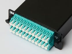
Today, MPO technology is commonly found in cassette-based data center physical layer installations. It is generally installed as a preterminated plug-and-play system based on duplex connectivity running 1G or 10G links. It is not yet widely deployed as a transceiver interface. New 40G multimode Ethernet transceivers will be based on the MPO format. This marks a major change brought about by the IEEE 40/100G standard.
In typical current implementations, MPO plug-and-play systems split a 12-fiber trunk into six channels that run up to 10 Gigabit Ethernet (depending on the length of the cable). The upgrade path for this type of system entails simply replacing the cassette with an MPO-to-MPO adapter module. The 40G system then uses the 12-fiber trunk to create a Tx/Rx link, dedicating four fibers for 10G each of upstream transmit, and four fibers for 10G each of downstream receive. Depending on the configuration, the remaining four fibers are dark, but they may be used in future upgrades.
3) Not all AOCs are created alike.
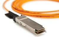
Active optical cables (AOCs) were developed about five years ago to supplement copper cables in data centers and high-performance computing environments. They were designed to bypass the bulk and distance limitations of copper. AOC cable assemblies use the same interfaces as their copper counterparts (QSFP and CXP for 40/100G) and are typically used in data centers for reaches of more than five meters.
An AOC consists of a bend-insensitive multimode or singelmode fiber cable terminated with a connector and embedded with transceivers that convert electrical signal to optical signal and back again. The most commonly used 40G-compatible AOCs used today in the data center are four-channel multimode Om2+ or Om3 fiber capable of 10G per channel and terminated with a QSFP+ connector. AOC cable assemblies have been designed to support a number of protocols, and they can be used for rack-to-rack, shelf-to-shelf and storage applications and on optical backplanes, hubs, router and servers. Generally speaking, data center managers seem to appreciate the affordability of a plug-and-play, high-bandwidth 40G link that AOC offers.
While many brands of AOCs are available on the market, all are not alike. As data rates increase, concern over power consumption and heat generation will increase. Low-power AOC cable assemblies and transceivers will become more and more important as data center operators strive to lower carbon footprint and energy costs.
In the past few years, cable assembly manufacturers have responded by releasing increasingly efficient AOC interconnects. For example, 3M makes a QSFP+ AOC assembly that uses approximately 475mW per end.
In addition to lowering power consumption directly, low-power AOCs release less heat than higher-powered products, further driving down power consumption by reducing the need for cooling.
Another issue to consider when choosing an AOC is reliability. As data rates increase and customers become less tolerant of errors and failure, the reliability of all equipment becomes more critical. The tiny electronics embedded in the transceiver, which enable the electrical-optical-electrical conversion, carry a potential for failure. Data center decision makers are wise to choose an AOC vendor that can show testing confirming its product’s reliability and that has a proven track record of producing robust products.
4) There is a still a place for copper in the 40G data center.
Passive copper cabling remains the preferred alternative for short-reaches in the data center, such as top-of-rack applications, and that won’t necessarily change as speeds increase. Copper cable assemblies are significantly more affordable than fiber, and many twinaxial cables available on the market today can support 40G (10G x four channels) for reaches of seven meters or less, per 40GBASE-CR4 specification.
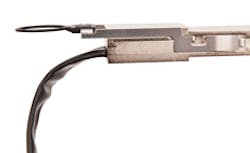
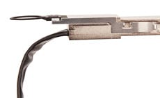
The problem with standard twinaxial cables is not their performance as much as their tendency to be stiff and bulky, thus consuming precious rack space and blocking critical airflow (reasons why AOCs were invented.) However, a recent innovation in manufacturing technology allowed the development of a thinner, uniquely shielded ribbon-style twinaxial cable that can support speeds of 10G per channel while addressing many of the concerns associated with round, bundled cable.
A standard round twinaxial cable is typically 4-mm to 8-mm thick. At only 0.88 mm thick for a single ribbon of 30 AWG (American Wire Gauge) cable, the recently developed ribbon-style twinaxial cable is significantly slimmer than its round counterparts. Even better, the cable can be folded multiple times and still maintain signal integrity, allowing for higher density racks and space savings.
While round cables offer some limited ability to bend around corners, designers must be careful not to bend the cables too much because the cable’s shielding and overwrap materials can distort the precise cable geometry needed to maintain impedance control, which can degrade signal performance. Moreover, the wrapped shield, with repeated breaks in the shield along the cable length, can produce an unwanted resonance effect, evident at certain frequencies.
The new ribbon-style cable replaces the traditional wrapped shielding with a shield structure that is continuous in both the transverse and the longitudinal directions. This shield design provides a transmission path with no significant resonances up to 43 GHz, even when folded or bent.
Cabling the 40G data center will likely include using a combination of methods and media. Choosing the right ones for the right areas of the data center will go a long way to achieving reliable 40G speeds in the most cost-effective manner. ::
Jeff Bullion is business development manager in 3M Electronic Solutions Division and Gordon Wiegand is business manager with 3M Communication Markets Division (www.3m.com/telecom).


