A tour of a copper wire and cable manufacturing plant informs us of the complex processes involved in making this fundamental product.
Arlyn S. Powell, Jr.
Copper wire and cable are the primary media that most cabling contractors install and most cable-plant managers are responsible for maintaining. And yet, although we work with these products day in and day out, have we ever asked ourselves, "Where does copper wire come from? How is it made?"
Journalists frequently get invited on press tours of manufacturing facilities, but it is rare for the working man or woman to have that opportunity, even if he or she has the time. So, we`re going to take you on a brief tour of the copper-wire and copper-cable manufacturing facility of Cable Systems International (csi) in Phoenix, AZ. Although csi makes a number of different wire and cable products (including Category 3 premises cable and Category 5 plenum cable), we`re going to look at the process for making plastic insulated cable (pic), which carries telephone and data circuits from the central office or distribution cabinets to neighborhoods or buildings.
Wire draw is first step
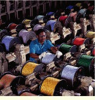
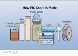
The first step in the manufacturing process takes place at wire draw #1. Here 15,000-pound coils of 5/16-inch (or 2 American Wire Gauge) copper rod from nearby Arizona copper mines are reduced to copper wire (see "Where does csi get its copper?," page 58). During the wire draw, the copper rod is pulled through a series of synthetic diamond dies, which gradually decrease in size. The rod and dies are flooded with a coolant and a synthetic lubricant to increase the life of the dies and keep the copper wire from overheating. The result is a 5000-foot coil of 10-, 12-, or 14-awg copper wire.
The coil of copper wire is then transferred by overhead crane to the insulating area of the plant, where a single coil may feed an insulate line for as long as two days. Each insulate line performs several different functions, including additional wire drawing and annealing as well as application of insulation.
The first step in this process is to further reduce the size of the copper wire by drawing it through wire draw #2. Operating the same way as wire draw #1, this process makes use of diamond dies to reduce a 10- or 12-awg wire to one 19-, 22-, 24- or 26-awg wire.
After wire drawing, the wire is extremely brittle and can easily be fractured if flexed. Since finished copper wire must be flexible, the wire is softened, or annealed, at this point. Annealing is accomplished by passing a large electrical current through the wire for a fraction of a second, raising its temperature briefly to 1000oF. To prevent oxidation of the wire, this step is performed in water. The water bath also cools and cleans the wire in preparation for the insulating step.
The wire, now soft and flexible, is passed through an extruder, where either a single or double coating of plastic is applied. High-density polyethylene pellets, colored one of ten industry-standard colors, are fed into the cool rear section of the extruder; as they are pushed forward, they are heated until they melt. Exiting the extruder, the coated wire, now traveling at approximately 60 miles per hour, passes through another cooling trough and is coiled on takeup reels.
Before the reels move to the next manufacturing operation, wire and insulation diameter are measured, and the wire is tested for such electrical properties as capacitance and resistance.
Described briefly, as they are here, these processes may sound simple, but given the range of products manufactured by csi and the varying mechanical and electrical requirements for each, the jobs of the technicians operating the manufacturing equipment can be quite complicated. On the insulate line, for example, new operators go through a 10- to 12-week training program that includes both classroom instruction and work experience on the plant floor. An on-the-job certification process follows. Insulate supervisor Norm Odom says that it takes months to develop the competency just to run the insulate lines. "Yet," he adds, "an operator could be here for 25 years and still encounter challenging and sometimes baffling scenarios--there`s just always something to learn at insulate."
Twisting and stranding
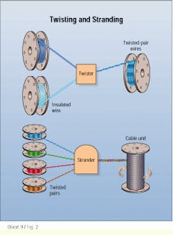
In the next step, the insulated wires are twisted into wire pairs--the ten standard insulation colors combined into 25 different industry-standard pair combinations. At twist, two wires of the same gauge are twisted together using a proprietary formula to determine twist length. Twist lengths vary from two to seven inches, with the unit of change being 1/10-inch.
Each different pair combination of insulation colors has a unique twist length, so that when different twisted pairs are combined in the same cable, no two side-by-side pairs will have the same twist length, a situation that can lead to crosstalk and interference (see "Does manufacturing matter? The case of crosstalk," page 50).
Because the twist operation, which involves the repeated transfer of steel reels of insulated and twisted wire, is physically demanding, csi trains new twist operators to use ergonomic lifting techniques and urges them to participate in a voluntary stretching program. Says new operator Lee Martinez, "The ergonomic lifting techniques that I learned in the operator certification program definitely helped prepare me for the physical demands of the job--especially when my assignment is to twist 26-gauge wire."
It requires two operators to run one stranding machine. The first operator takes the reels of twisted pairs and sets them up on a supply stand in the proper color-coded order and twist-length sequence. The pairs are then fed through a rotating, oscillating faceplate that is designed to prevent the same twist patterns from being placed side by side in the finished cable.
As the pairs continue through the stranding machine, the second operator oversees their grouping into 25-pair subunits, which are wrapped with a distinctive color-coded binder for identification. For larger cables, such as the 300-, 900-, 1500- and 1800-pair cables used by telephone companies, the subunits are combined into 100-pair units, which again are wrapped with a color-coded identification binder.
The unit is passed through a device called a flyer bow, which applies additional twist, making it more flexible and further decreasing the chance of electrical interference. It is then placed on a unit truck and tested for electrical defects such as crosses, shorts, and opens. For smaller cables, a 25-, 50- or 100-pair unit may form the core of the cable. In this case, the unit truck with the core on it is taken directly to the jacketing operation once the cable passes its electrical testing. If the unit is to form part of a larger cable, it next goes to the cabling operation.
Cabling and jacketing
At cabling, the units coming from the stranding operation are grouped together to form a multi-unit cable core. The process is similar to stranding--the units are passed through a faceplate that properly positions them in the cable core. The units are also twisted together on a rotating core truck to help control electrical interference and provide flexibility.
For air-core cables, the core wrap is applied at the cabling station. (Pressurizing the cable helps it resist the intrusion of moisture. A more dependable technique for preventing moisture from getting into a cable is to fill it with a gel-like filling compound. If the cable is to be gel-filled, the core wrap is applied after the filling compound is forced into the cable core. Depending on the technique preferred, the filling compound can be applied at the cabling station or during the next operation--jacketing.)
As mentioned, smaller, single-unit cable cores may come to the jacketing operation directly from stranding; larger, multi-unit cable cores go through the cabling operation before being sent to jacketing. At jacketing, several operations--gel-filling, armoring, jacketing, and printing--are performed to produce the finished cable.
The first step is for the filling compound to be added (for gel-filled cables). The cable core is heated to ensure that the filling compound penetrates all open spaces in the core. The heated core passes through the filling chambers, where the filling compound is added. And finally, a plastic core wrap is applied.
Both air-core and gel-filled cables used in outside-plant applications are armored, the next phase of jacketing. Depending on the cable design, a protective metal sheathing of either aluminum or aluminum and steel combined may be added during this manufacturing step. The aluminum acts as a grounding path for high-voltage surges that may be caused by lightning strikes and other eventualities in aerial cables, while steel adds mechanical protection for buried cable against pests such as rats and gophers. In most outside-plant cable designs, the metal sheathing is corrugated for added flexibility and coated with a flooding compound that protects the metals from corrosion and moisture damage.
The outer cable jacket is extruded in the next step. It is usually made from low-density polyethylene, black in color and resistant to ultraviolet light in case it is exposed to sunlight. This rugged plastic is the final protection for the enclosed cable against the environmental conditions underground or when strung to utility poles.
The jacketed cable then passes through a temperature- controlled water trough, which cools the jacket. The cable is dried, and the top layer of the jacket is heated slightly so that printer markings can be imprinted on it. Because of the heating, the markings are stamped into the jacket itself and will last the life of the cable.
Cables tested before shipping
Upon exiting the jacketing operation, the finished cable is wound onto metal or wooden reels and then transported to the final test facility.
Before electrical testing begins, each cable is given a final test for physical construction. An inspector checks for proper placement of units, subunits, and spare pairs within the cable. Electrical tests include a ringout of all conductors for continuity, and a core-to-sheath test. The core-to-sheath test measures minimum voltage requirements between the cable core and the metal sheath; this helps ensure that high-voltage surges, such as lightning strikes, cannot reach the conductors. A high-voltage test is also performed, and all conductors are checked for electrical integrity. Random tests are performed for mutual capacitance, unbalance, and resistance.
According to final-test shift supervisor Joe Long, "If there`s a quality defect, we want to find it first, instead of the customer. And when we do find a defect, we send a sample of it, along with any applicable feedback, back through the production process--to help prevent the same type of defect from happening again."
Preparing the cable for shipment may include sealing the cable end with a steel or plastic cap, and testing air-core cables for integrity. Such cables are equipped with valves so that dry, pressurized air can be pumped into them to protect them from moisture. Air-core cables are monitored for 24 hours to ensure that there are no leaks.
Customers may also request that their cables be equipped with pulling eyes, cleaned ends, or factory preconnectorization.
Providing quality products and serving the customer are constant themes as one talks to the operators, supervisors, and engineers in csi`s pic shop. As a final commitment to quality, final-test employees sign the customer-response cards that go out with each order, so that customers can contact the individuals who processed their particular orders in case there are questions.
Much of the technical information and the graphics in this article were taken from csi`s company newsletter, csi Today, and particularly from the four-part "From Copper to Cable" series run in the March/April to September/October 1996 issues.
Machine operator Reggie Dirks loads a stranding machine with twisted wire pairs before they are stranded into cable cores and units.
In the first phase of the manufacturing process, copper wire is drawn to the proper size in a two-step drawing process, and then it is annealed and coated with polyethylene insulation. It is tested before passing on to the next manufacturing phase.
In the second manufacturing phase, insulated copper wire is first twisted into wire pairs, and then the twisted wire pairs are combined by a strander.
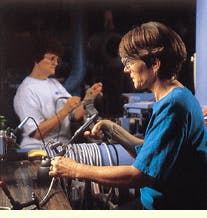
Virginia Allwine (foreground) and Nancy Brown (background) are production specialists who terminate cables using wire wrap and soldering for Cable Systems International (csi--Phoenix, AZ). The cables are used in customer premises and central-office applications.
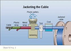
During the jacketing operation, a cable core may be wrapped with plastic and armored with metal before the outer jacketing is extruded. The jacketed cable is then tested, cooled, and wrapped onto reels.
Does manufacturing matter? The case of crosstalk
We`ve all experienced crosstalk at one time or another when on the telephone--that annoying situation where you can hear someone else`s conversation on your line. Several technical developments have reduced the incidence of crosstalk on voice circuits, but the key to controlling this problem remains proper design of the cable.
Crosstalk results when one voice circuit picks up the signal from another, nearby circuit; the conversation literally jumps from one wire pair to the other. If each wire pair is twisted at a different rate, however, the probability of crosstalk problems is very low.
Administering different twist rates to each wire pair in a cable begins at the twist operation, where each twisted-pair color combination is assigned a unique twist gear. This gear determines the length of each completed twist of the wire pair. In the following stranding operation, each color combination is assigned a unique position in the faceplate in such a way that different twisted pairs are grouped with other pairs with which they are harmonically compatible.
If twist lengths or faceplate positions are accurate, crosstalk does not occur. If inaccurate, the pair or cable must be scrapped, because there is no ready method to repair this problem.
Cables are tested periodically during manufacture to demonstrate conformance to the quality standards necessary to prevent crosstalk. However, only spot checking is possible, since the crosstalk test takes between 2.5 and 7 hours to conduct.
Where does CSI get its copper?
The amount of copper wire that Cable Systems International (csi--Phoenix, AZ) produces each week would, if laid end-to-end, stretch to the moon and back. Most of the copper for this wire comes from the nearby bhp Mines and the Cyprus Copper Mines (both in Arizona), where it is refined to a purity of 99.6% before being shipped to csi. At this point, the major impurity in the copper is oxygen, which improves the ductility of the copper. Cyprus and bhp cast and roll their copper into large coils, which are trucked to csi three at a time--a 22-ton load.
Cabling Installation & Maintenance
Editorial Mission
Installers of premises and campuswide communications systems face constantly evolving standards, products and technology. Keeping pace with these changes requires access to current information from informed peers who are knowledgeable in fiber and copper technology relative to premises communications. Cabling Installation & Maintenance provides peer-to-peer perspective in its interpretation of standards and technology, its presentation of installation techniques and in the selection and use of products in premises communications.
