Using multi-cell conduit in the outside plant
Using multi-cell conduit in the outside plant
For expanding capacity needs, multi-cell conduit leaves room to spare.
Paul R. Metcalf
When building a new campus network infrastructure, designers should plan for a 15-year timeframe. This is a challenge because there is no way to know what technology will evolve during that period. However, good estimates made with existing technology will most likely provide sufficient capacity.
Many campuses have existing power and telecommunications infrastructure. On the one hand, this can be used to advantage as a path along which the new telecommunications conduit can be installed. On the other hand, it can inhibit the expanding system, depending on its location. The designer should obtain drawings of the existing infrastructure to facilitate the installation of new conduits. Knowing the location of the existing conduits is very important because they can either be avoided or added to the new system. By locating the existing infrastructure, installers can avoid digging into an existing line, which results in expensive repair costs.
The purpose of a telecommunications conduit is to facilitate the installation of fiber or copper telecommunications cable and offer protection for it after the installation is complete. Conduit can be either single-cell or multi-cell. Multi-cell conduit systems typically include three or four cells, or innerducts. The three-cell variety typically is made of 11/4-inch-diameter innerducts, enabling larger cable to be installed. Four-cell conduit offers 1-inch-diameter innerducts. Both sizes of cells are placed inside a 4-inch outer duct.
One of the benefits of using multi-cell conduit is that you can add extra cable capacity at the initial installation. As the network specifications develop, if only two or three innerducts are required for current needs, installers can add extra, or blank, innerducts. They facilitate future installation of cable as the needs of the infrastructure grow or if leasing a duct bank to a third party becomes an option.
Pull and push techniques
Cable is installed by either pulling or pushing it into the innerducts. Pulling, which has been used for many years because of its simplicity, can be done in a one- or two-step process. Using the one-step method, the cable can be pulled in using an air-propelled rubber missile attached directly to the lead end of the cable. The two-step method requires that a cord (rope or tape) first be blown into the innerduct using a missile. The cable is then attached to the cord and a winch is used to generate pulling forces.
Pushing technology, also called "cable jetting," uses a combination of mechanical feeder tracks and compressed air. The feeder tracks--either hydraulically or pneumatically driven--feed the cable off its reel and push it into the duct. Compressed air is forced through the innerduct at the point of cable entry. When the air moves over the outside of the cable it creates friction, or drag, which pushes the cable through the duct.
The advantages of cable jetting have led to its significant growth in the past few years. It places almost no strain on, and thus reduces damage to, the cable because it is not being pulled. Furthermore, cable jetting runs are longer than those of any other method. Cable runs more than two miles long have successfully been completed using cable jetting. This ultimately results in longer distances between manholes or handholes, lowering overall installation costs and minimizing the potential for cable damage. Even for shorter runs, jetting technology is often preferred.
When you are considering the telecommunications conduit, the number and diameter of cables must be determined before the innerduct size and quantity can be selected. Future growth must also be considered. Once these factors are known, the number of innerducts can be determined. Single or multiple multi-cell conduits can be installed in banks as required.
Outer duct is available in several materials. Installers should select a material type based on the application, protection required, and preference of the specifiers. Polyvinyl chloride (pvc) is offered in Type C, 40, and 80 wall thicknesses, any of which can be installed above or below ground. Type C is the least expensive, has the thinnest wall, and is best for direct-burial and concrete-encased applications. Thicker pvc Type 40 wall offers more protection. Type 80, which is very rigid and has the thickest pvc wall available, is the most resistant to crushing or other physical damage.
Fiberglass conduit is a good solution for under-bridge applications and where lightweight, strong outer duct is required. It comes in three wall thicknesses. The toughest is bullet-resistant wall for mission-critical network applications. Steel outer duct is offered in electrical metallic tubing for premises applications and galvanized rigid conduit for above-ground or underground applications where the most protection is needed. Galvanized rigid conduit can be pvc-coated on the outside and urethane-coated on the inside to satisfy the toughest corrosion- resistant requirements for steel conduit. Steel and fiberglass conduit should not be considered for directional drilling installations because of their rigid properties. Most manufacturers of multi-cell conduit systems offer some or all of the above outer duct materials, making it convenient to order a variety of materials from one source.
Installation methods
There are two primary means of installing underground conduit in a campus environment: trenching and boring. Trenching allows conduit to be laid into place and separated by spacers, depending on the quantity per trench. Once the conduit is in place, the duct bank is covered with fill or concrete and the landscape is restored.
Boring, formally referred to as horizontal directional drilling (hdd), is a rapidly growing method for installing many different materials, including electrical conductors and telecommunications cable. The process involves boring a hole horizontally underground using a machine designed for this purpose. Its popularity has grown rapidly because of its convenience and speed of installation. Rather than cutting through a street, hdd lets you drill under it. Unlike trenching, the need to repair the landscape is largely eliminated because the only areas that need restoration are the pipe entry and pipe exit holes. Most drilling done on a campus environment would typically be less than 1000 feet in length. However, the technology can be used to drill holes several feet in diameter for lengths far beyond 1000 feet.
Caution should be used when boring multi-cell conduit because it has not been specifically designed for directional drilling loads and it has its limitations. But end-users have made it work, and with the popularity of hdd growing quickly, manufacturers are working to increase the strength of telecommunications conduit for this application. Some manufacturers already offer 4-inch pvc, Type 40 boreable outer duct designed specifically for up to 1000-foot directional drilling applications.
When hdd is used as the installation method, the pipe being installed must be somewhat flexible. Because of its flexibility, strength, and resistance to crushing, pvc is the best option and can be bored in Type C and 40 wall thicknesses. Type C should only be used for about 300-foot bores, and Type 40 for slightly longer bores, depending on the soil conditions. Gluing and using screws to hold the joints together is recommended to maximize the joint strength.
Building entry points
Campus environments require the connecting of numerous buildings where straight lengths of pipe are joined together and then enter a building. Many of the building entry points are made underground. If other utilities have already been installed and have to be avoided, the direction of entry into a building is not entirely under the installer`s control. Several manufacturers offer a solution to this problem: a field-bendable pipe that offers the flexibility to make whatever radius and angle bend is required. It is made with a corrugated outer duct and has three or four innerducts. This product makes specifying conduit and installing bends much easier because it eliminates the need to try to purchase a rigid elbow with a specific radius and angle. The easiest way around obstacles may be with a flexible, corrugated section of multi-cell conduit.
One of the most important recommendations for the design and installation of multi-cell conduit systems is to minimize the number of bends. Friction on cable is significantly higher when it is pulled around a bend--whether it is a minor undulation or a 90o angle--than through a straight section. To prevent damage from elevated temperatures generated when pulling cable around bends, some manufacturers use heat-resistant mat-erials for innerducts. Nevertheless, to increase the distance that cable can be pulled or jetted, try to make conduit runs as straight as possible.
Lee Edmark, facilities planner at the University of North Carolina at Chapel Hill, says, "We try to limit the number of bends between manholes to a maximum of 180o combined in a run of multi-cell conduit. When this rule is followed, we don`t have problems with cable installation. When planning the connection to a manhole beside a building, be sure that the depth of the trench or incoming multi-cell conduit is deep enough so the end of the bend coming into the manhole is flush with the manhole wall. Because the radius of the bend is relatively large, the end often comes up too high." With a little planning and experience, installation of bends in a multi-cell conduit system can easily and successfully be installed.
American Polywater Corp. (Stillwater, MN--www.polywater.com) provides software that is a valuable tool in designing effective multi-cell conduit systems.
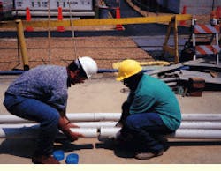
Multi-cell conduit can be assembled easily. Glue is not required because of the rubber gaskets, which keep out water and hold the joints together, speeding assembly.
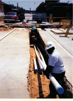
Banks of multi-cell conduits can be installed in a trench for concrete encasement or direct burial. The conduit can be easily moved around a job site. Protective caps prevent soil from entering the innerducts and reduce the possibility of damage to the cable during installation.
A combination of rigid conduit and flexible bends can be used to direct the path of the multi-cell conduit into buildings and around utilities. A flexible, corrugated pvc bend offers the versatility to easily reposition the conduit in the field, minimizing the number of different parts that have to be specified.
Paul R. Metcalfe is outside-plant manager at Carlon, a Lamson & Sessions Co. (Cleveland, OH).


