A technical support team explains the TIA/EIA-607 standard and offers solutions.
Anixter Inc.'s (www.anixter.com) Levels Lab is primarily concerned with the science behind the standards and the development of new methodologies to test and enhance that science. A technical support team was established to provide simple explanations and practical solutions to the problems encountered by customers. This article from the Levels Lab's Technical Support Team discusses commercial building grounding and bonding networks and how to design them.
Commercial building requirements
Following the AT&T divestiture of 1984, the end user became responsible for all premises cabling of voice and data. Advancements in voice communications and the convergence of voice and data have led to increasingly complex interactive systems owned and maintained by the end user. These systems require a reliable electrical ground-reference potential.
Grounding by attachment to the nearest piece of iron pipe is no longer satisfactory to provide ground reference for sophisticated active electronics systems. Bonding is the provision of good grounding connections between elements of the grounding network. Secondary power protection is also recommended for delicate electronics.
Every telecommunications network requires a dedicated grounding and bonding system as described in the Commercial Building Grounding and Bonding Requirements for Telecommunications (ANSI/ TIA/EIA-607) standard, which provides minimum recommendations for such a network.
A network of this type may also be used for grounding of access and service provider equipment, data centers, broadband video distribution, security, fire, and other systems. Unfortunately, due to a general lack of familiarity with the standard, this vital grounding network is often overlooked in preparing the network design and subsequent bid requests.
Design considerations
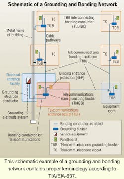
A grounding and bonding network can be described as a "tree-shaped" or "star-wired" configuration of insulated copper conductors that parallel the telecommunication cable distribution and link rooms containing telecommunication equipment to a common ground. The recommended copper conductors to be used are robust in size. Branches are 6 AWG (American wire gauge, 0.1620-inch diameter). Backbone runs are commonly 2/0 AWG (0.3648 inches) or 3/0 AWG (0.4096 inches).
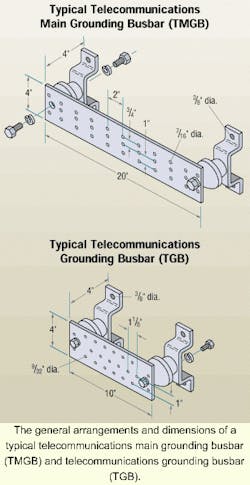
Solid copper grounding busbars are installed with insulated standoffs in the equipment room (minimum 1/4x4 inches by variable length), as well as in each telecommunications room or entrance facility (minimum 2 inches high is sufficient here). Each copper busbar is purchased pre-drilled with rows of holes for attachment of bolted compression fittings.
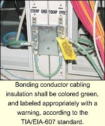
Active telecommunication equipment, frames, cabinets, raceways, and voltage protectors are typically grounded to these busbars with insulated stranded copper cable (minimum 6 AWG) with crimped-on lugs at each end. Two-hole lugs are often preferred for bonding at the busbar. Single-hole lugs are used at the equipment cabinet.
The busbars are connected together with a backbone of insulated stranded (or solid) copper cable (a minimum of 6 AWG is required, and size 3/0 AWG or larger should be considered). This backbone is connected to a main grounding busbar in the telecommunications equipment room, which is bonded to the electrical service entrance ground and an earth ground. The backbone extends from the equipment room to busbars in each individual telecommunications room. The grounding system is also bonded to building structural steel on each floor.
How to estimate a grounding and bonding system
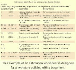
Here is a step-by-step example for estimating a grounding and bonding network:
- Quote one main grounding busbar for the equipment room.
- Quote one grounding busbar for each telecommunications room and the electrical en trance facility. Mounting hardware is included, but anchor bolts may be required.
- Estimate distance from each busbar to its neighboring busbar and from the main busbar to the building electrical entrance facility. Total the distance in feet and add 20% and/or average up to the nearest 100 feet. Quote this length of #2/0-gauge backbone bonding conductor.
- Quote two large 2-hole grounding lugs for each busbar link to other busbars, or to building steel (on each floor), plus 20% spares.
- Quote two 3/8- 16 (threads per inch) cap screws, 1 inch in length, each with two flat washers, lock washer, and nut for each large lug, plus 20% spares. Copper-plated steel is recommended, but cadmium or zinc plating is acceptable.
- Estimate how many ladder racks, frames, cabinets, raceways, and active electronics will be grounded to the local busbars. Estimate a distance in length for each bonding conductor (about 12 feet). Multiply the number of conductors by this calculated average length, and then add 20% and/or average up to the nearest 100 feet. Quote this length of #6-gauge bonding conductor.
- Quote two medium single-hole grounding lugs for each busbar link to other racks, frames, cabinets, raceway, and active electronics, plus 20% spares. (A 2-hole grounding lug is also available to meet telephone company specifications.)
- Quote one 1/4- 20 (threads per inch cap screw, 1 inch in length, with two flat washers, lock washer and nut for each medium lug, plus 50% spares. Once again, copper-plated steel is recommended, but cadmium or zinc plating is acceptable.
- Quote one plastic warning label for each busbar location, and two for each bonding conductor, plus spares.
- Quote one alphanumeric identification label for each system element and lug, plus spares (pre-printed wire numbering booklets).
Investigate your own applications
Because of the variety of uses for the products described here, those responsible for the application and use of these products must be sure that all necessary steps have been taken to assure that each application and use meets all performance and safety requirements-including any applicable laws, regulations, codes, and standards. (Any illustrations, charts, sample materials lists, and layouts shown here are intended solely for purposes of example.)
Frank Dickman is an RCDD manager of technology for Anixter Inc. (Skokie, IL). He is the voting member for Anixter on behalf of customer interests at several standards development organizations.


