BY DAVID KOZISCHEK AND DOUG COLEMAN, CORNING CABLE SYSTEMS
With the continued requirement for expansion and scalability in the data center, cabling infrastructures must provide reliability, manageability and flexibility. Deployment of an optical connectivity solution allows for an infrastructure that meets these requirements for current and future data rates. A key factor when choosing the type of optical connectivity is scalability. Scalability refers to not only the physical expansion of the data center with respect to additional servers, switches or storage devices, but also to the scalability of the infrastructure to support a migration path for increasing data rates. As technology evolves and standards are completed to define data rates such as 40- and 100-Gbit Ethernet, 32-Gbit and higher-speed Fibre Channel, and 40-Gbit and higher-speed InfiniBand, the cabling infrastructures installed today must provide scalability to accommodate the need for more bandwidth in support of future applications.
One- and 10-Gbit/sec data rates are not adequate to meet the future needs of high-bandwidth applications. The requirement for higher data rates is being driven by many factors. Switching and routing, virtualization, convergence and high-performance computing environments are examples of where these higher network speeds will be required within the data center environment. Additionally, Internet exchanges and service provider peering points and high-bandwidth applications, such as video-on-demand, will drive the need for a migration from 10- to 40- and 100-Gbit interfaces.
| 850-nm Ethernet distance (in meters) | ||||
| 1G | 10G | 40G | 100G | |
| OM3 | 1000 | 300 | 100 | 100 |
| OM4 | 1000 | 550 | 150 | 150 |
IEEE 802.3ba ratified
The Institute of Electrical and Electronics Engineers (IEEE; www.ieee.org) 802.3ba 40G/100G Ethernet standard was ratified in June 2010. The standard provides detailed guidance for 40/100G transmission with multimode and singlemode fibers. The standard does not have guidance for Category-based unshielded twisted-pair or shielded twisted-pair copper cable.
OM3 and OM4 are the only multimode fibers included in the standard. Multimode fiber uses parallel-optics transmission instead of serial transmission due to the 850-nm vertical-cavity surface-emitting laser (VCSEL) modulation limits at the time the guidance was developed. Singlemode fiber guidance uses duplex fiber wavelength division multiplexing (WDM) serial transmission. 40/100G multimode fiber physical media dependent (PMD) variants continue to offer a significant value proposition compared to singlemode fiber PMDs for short-length interconnects in the data center.
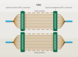
Parallel-optics transmission, compared to traditional serial transmission, uses a parallel optical interface where data is simultaneously transmitted and received over multiple fibers. The 40G and 100G Ethernet interfaces are 4x10G channels on four fibers per direction, and 10x10G channels on 10 fibers per direction, respectively.
The table on page 19 provides the OM3- and OM4-specified distances for Ethernet. Each distance assumes 1.5 dB total connector loss with the exception of OM4 40G/100G, which assumes 1.0 dB total connector loss. OM3 and OM4 are fully capable to support legacy and emerging data rates, as a 15- to 20-year service life is expected for the physical layer.
| IEEE | Designation | Mbits/sec | Fiber type | Number of fibers | Maximum link length (in meters) | Maximum channel insertion loss (in dB) | |
| 10-Gbit Ethernet | 802.3ae | 10GBase-SR | 10,000 | OM3 | 2 | 300 | 2.6 |
| 40-Gbit Ethernet | P802.3ba | 40GBase-SR4 | 40,000 | OM3 | 8 | 100 | 1.9 |
| 40-Gbit Ethernet | P802.3ba | 40GBase-SR4 | 40,000 | OM4 | 8 | 150 | 1.5 |
| 100-Gbit Ethernet | P803.2ba | 100GBase-SR10 | 100,000 | OM3 | 20 | 100 | 1.9 |
| 100-Gbit Ethernet | P802.3ba | 100GBase-SR10 | 100,000 | OM4 | 20 | 150 | 1.5 |
When evaluating the performance needed for the OM3 and OM4 cabling infrastructure to meet the requirements for 40G and 100G Ethernet channel insertion loss transmission, three criteria should be considered: 1) bandwidth, 2) total connector insertion loss, and 3) skew. Each of these factors can impact the cabling infrastructure's ability to meet the standard's specified transmission distances.
Bandwidth. OM3 and OM4 fibers were selected as the only multimode fiber for 40G/100G consideration. The fibers are optimized for 850-nm transmission and have a minimum 2000 MHz.km and 4700 MHz.km effective modal bandwidth (EMB), respectively. Two EMB measurement techniques are used today for the bandwidth measurement. The minimum effective modal bandwidth calculated (EMBc) method, in our opinion, offers a more reliable and precise measurement compared to the differential mode delay (DMD) mask technique. With minEMBc, a true scalable bandwidth value is calculated that can reliably predict performance for different data rates and link lengths. With a connectivity solution using OM3 and OM4 fibers that have been measured using the minEMBc technique, the optical infrastructure deployed in the data center will meet the performance criteria set forth by IEEE for bandwidth.
Insertion loss. Insertion loss is a critical performance parameter in current data center cabling deployments. Total connector loss within a system channel impacts the ability of a system to operate over the maximum supportable distance for a given data rate. The 40G and 100G Ethernet standard specifies the OM3 fiber 100-meter distance maximum channel loss to be 1.9 dB, which includes a 1.5-dB total connector loss. The OM4 fiber 150-meter distance maximum channel loss is 1.5 dB, which includes a 1.0-dB total connector loss budget. The insertion loss specifications of the MPO connectivity components should be evaluated when designing data center cabling infrastructures. With low-loss MPO connectivity components, maximum flexibility can be achieved with the ability to introduce multiple connector matings into the connectivity link such that structured cabling architectures can be supported.
Skew. The IEEE 802.3ba standard includes an optical media skew of 79 ns. Optical skew–the difference in time of flight between light signals traveling on different fibers–is an essential consideration for parallel-optics transmission. With excessive skew, or delay, across the various channels, transmission errors can occur. Skew testing on MPO connectivity solutions has demonstrated compliance to a strict 0.75-ns skew requirement as defined in the InfiniBand standard. Deployment of a connectivity solution with strict skew performance ensures compatibility of the cabling infrastructure across a variety of applications. When evaluating optical cabling infrastructure solutions for 40G/100G applications, selecting one that meets the 0.75-ns skew requirement ensures performance not only for 40G/100G, but also for InfiniBand and future Fibre Channel data rates. Additionally, low-skew connectivity solutions validate the quality and consistency of cable designs and terminations to provide long-term reliable operation.
Optical cabling for 40G and 100G
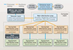
Recommended cabling infrastructure deployments in the data center are based on guidance found in TIA-942 Telecommunications Infrastructure Standard for Data Centers. Using a distributed star topology in a structured cabling implementation provides the most flexible and manageable infrastructure. Many data center deployments today use the reduced topology described in TIA-942 where the horizontal distribution areas (HDAs) are collapsed into the main distribution area (MDA). In this collapsed architecture, the cabling is installed between the MDA and the equipment distribution areas (EDAs).
For optimized performance in meeting data center requirements, the topology of the cabling infrastructure should not be selected alone; infrastructure topology and product solutions must be considered in unison.
Cabling deployed in the data center today must be selected to support data rate applications of the future, such as 100G Ethernet, Fibre Channel ≥32G and InfiniBand ≥40G. To do this, OM3 or OM4 fiber is a must. In addition to being the only multimode fibers included in the 40G and 100G Ethernet standard, OM3 and OM4 fibers provide the highest performance as well as the extended reach often required for structured cabling installations in the data center.
In addition to the performance requirements discussed, the choice in physical connectivity is also important. Because parallel-optics technology requires data transmission across multiple fibers simultaneously, a multifiber (or array) connector is required. Using MPO-based connectivity in today's installations provides the means to migrate to this multifiber parallel-optic interface when needed.
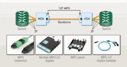
Factory-terminated MPO solutions allow connectivity to be achieved through a simple plug-and-play system. To meet the needs of today's serial Ethernet applications, MPO-terminated backbone/horizontal cabling is simply installed into preterminated modules, panels or harnesses.
Cabling migration from 10G to 40G to 100G in an MPO-based system is a simple and easy deployment. Starting with 10G, a 12-fiber MPO cable is deployed between the two 10G switches. Modules are used at the end to transition from the 12-fiber MPO to LC duplex. This enables connectivity into the switch.
When the switches migrate to 40G, the module is removed and is replaced by a 12-fiber MPO adapter panel. The use of a 12-fiber MPO jumper is needed to establish connectivity between the switches.
Future 100G networks will require a 24-fiber MPO jumper to establish a link. Systems that use 12-fiber MPO backbone cabling will need a 24-fiber or two 12-fiber MPO jumpers.
Multiple loss-performance tiers are available for MPO connectivity solutions. Just as connector loss must be considered with current, deployed applications such as 10G Ethernet, insertion loss is also a critical factor for 40G and 100G Ethernet applications. For example, IEEE 802.3ae defines a maximum distance of 300 meters on OM3 multimode fiber for 10G Ethernet (10GBase-SR). To achieve this distance, a total link loss of 2.6 dB is needed with a maximum total connector loss of 1.5 dB. As the total connector loss in the channel increases above 1.5 dB, the supportable distance decreases the channel loss increases. When extended distances or multiple connector matings are required, low-loss performance modules and connectivity may be necessary. OM3 is bandwidth-limited beyond 300 meters.
Likewise, with the total connector loss for 40G and 100G Ethernet, similar considerations must be evaluated. MPO connector matings with maximum connector loss specifications of 0.5 dB and 0.35 dB provide alternatives for variations in the infrastructure design as the physical connectivity and channel distance are taken into account to make a final selection in product performance.
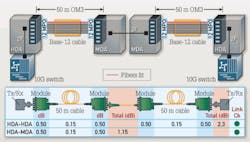
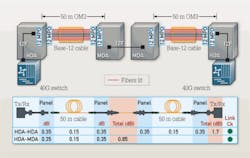
Link-loss migration from 10G to 40G and 100G in an MPO-based system is a simple and easy deployment.
In the illustrated example, two 50-meter links are connected from the MDA to the HDA. 10G switches are deployed, and the link loss is calculated from the HDA to the MDA and from one HDA to another. In this case, both links are below the 2.6-dB maximum for 10G.
As the network migrates to 40G, the link-loss requirements get tighter. In this example, two 50-meter links are connected from the MDA to the HDA. 40G switches are deployed, and the link loss is calculated from the HDA to the MDA and from one HDA to another. In this case, the losses of both links are below the 1.9-dB maximum for 40G on OM3 fiber.
As the network migrates to 100G, the link-loss requirements are the same as 40G. In this scenario, two 50-meter links are connected from the MDA to the HDA. 100G switches are deployed, and the link loss is calculated from the HDA to the MDA and from one HDA to another. In this case, both links are below the 1.9-dB maximum for 100G on OM3 fiber.
To best meet the needs of the future, MPO-based connectivity using OM3 and OM4 fiber is the ideal solution in the data center. With inherent modularity and optimization for a flexible, TIA-942-compliant structured cabling installation, MPO-based optical fiber systems can be installed for use in today's applications, while providing an easy migration path to future high-speed technologies such as 40G and 100G Ethernet.
DAVID KOZISCHEK is market manager, data centers and Doug Coleman is manager, technology and standards with Corning Cable Systems (www.corning.com/cablesystems).

