Can you prepare for present and future bandwidth needs with legacy multimode fiber?
By Kevin Lenglé, Ph.D., CAIlabs
Multimode fiber is most widely associated with short-haul transmission, and is particularly prevalent in enterprise and data center networks. In this article I will dispel some myths surrounding multimode fiber (MMF) and its intrinsic limited bandwidth. I will go into a little more depth on a new technological approach that allows users to leverage the full potential of MMFs and increase their bandwidth capacity, to futureproof existing campus cabling infrastructure. I’ll explain this relatively new trend and look at the future, with a particular focus on the opportunities it currently presents to the local area network (LAN) market.
Multimode fiber is by no means a new technology. Used in the telecommunications sector since the early deployments of the 1980s, it works by simply carrying light over a number of different paths, or modes. MMF is proven, particularly popular within data centers, as an economical way to provide high-speed connections between short distances, such as between servers, switches and storage. While the cost of MMF itself typically is higher than singlemode fiber (SMF), an end-to-end multimode infrastructure is considered cost-effective because the transceivers used are significantly less costly than those used with SMF, thanks to the use of vertical-cavity surface-emitting laser (VCSEL) technology. This is a crucial consideration, especially in terms of a data center’s running costs. In a large facility, for example, with thousands of links, a multimode active layer can provide real cost savings, from both a transceiver and power/cooling perspective.In terms of bit rates, new standards are continually being developed in order to propose 100-, 200-, or even 400-Gbit/sec transceivers to support the ever-increasing bandwidth needs within data centers. Laser-optimized OM3 and OM4 MMF composes a significant portion of data center infrastructure. These MMFs were instrumental in the development and standardization of the new type of MMF available today, OM5. This type of wideband MMF allows short-wavelength division multiplexing (SWDM). The SWDM Multisource Agreement Alliance believes that SWDM will allow data centers to increase their capacity while avoiding expensive infrastructure upgrades. By using OM5 fiber, users can transmit 40 Gbits/sec over 440 meters, or 100 Gbits/sec over 150 meters.
Multimode in LANs
Today when we talk about MMFs, we often talk about OM3/OM4/OM5 and about data center applications. What about legacy OM1 and OM2, mainly deployed within campus cabling infrastructure? Why focus an article on these older-generation MMFs? It’s because there is also a future for these old fibers. The latest industry innovations reveal the possibility to futureproof legacy MMF infrastructure by removing the MMFs’ bandwidth block in order to support evolving network speeds in these applications. Several vendors are launching new product lines based on this technology.
Within LANs, a growing number of applications require significant bandwidth in order to ensure successful transmission of large volumes of data, audio files, and video. Additionally, the growing number of mobile terminals, online devices and other connected devices in LANs have contributed to the need for higher bandwidth. Bandwidth-intensive applications and latency-sensitive traffic types are becoming ubiquitous in the LAN. As a result, it is necessary to be able to reliably transport these data streams with a high quality of services. We are not necessarily talking about hundreds of gigabits per second, as is the case in data centers, but rather, LAN speeds typically are 10 Gbits/sec and sometimes 40 Gbits/sec across links that connect floors or buildings.
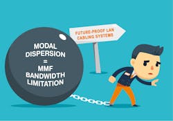
Most of the optical fibers deployed in a LAN are multimode. A large majority of deployed multimode optical fibers do not support throughput of 10 Gbits/sec over campuswide links, due largely to the optical design of this fiber type. Contrary to the active components of the network, for which upgrades can be carried out relatively easily, the optical cabling infrastructure has a performance envelope that generally could not be increased without physically changing the cable that carries the information, such as deploying a new generation cable like OM5 or singlemode. MMF possesses intrinsic performance limitations, which are inherent to its physical properties. More specifically, for multimode optical fibers widely installed in LANs, such as OM1 (62.5/125 µm) and OM2 (50/125 µm), high-speed transmission is limited as a result of modal dispersion. Modal dispersion is a distortion mechanism occurring in MMFs. Due to the different velocities of the modes, the signal is spread out and often deformed in time during the propagation in the fiber. This leads to inter-symbol interference and the inability to retrieve the data that was transmitted. The higher the transmitted throughput is, the greater the distortion is.
Combating dispersion
It should be noted that all MMFs are affected by modal dispersion, including OM3-OM4-OM5 fiber types. Certain optical properties of the fiber (especially the refractive index profile of the fiber) strongly impact the velocity of the different modes of propagation, causing modal dispersion. As glass transformation techniques have evolved over the years, there are different generations of graded-index multimode fibers (OMx), which decrease the differential mode delay between modes according to the fiber type and therefore the impact of modal dispersion on bandwidth. To sum up, modal dispersion degrades the width of the bandwidth capacity of the multimode optical fiber. For a given throughput, it reduces the distance that can be reliably attained between transmitter and receiver. As a result, standard transmission over MMF within the 850-nm operating wavelength with 10GBase-SR is limited to distances of up to 33 meters (36 yards) on conventional 62.5-micron OM1 fibers and 82 meters (90 yards) over conventional 50-micron OM2 fibers. And nothing is specified on this old type of fibers for bit rates above 10 Gbits/sec.
A typical solution that prevents throughput and distance limitations due to modal dispersion in currently deployed MMFs would therefore be to replace them with new-generation MMF or with SMF that does not experience modal dispersion. However, redeploying the fiber oftentimes is a difficult task, depending on a number of factors including distances involved. An audit of the cabling infrastructure is necessary in order to verify the availability and condition of cable duct In some cases civil engineering may be required to deploy new cable or to perform microtrenching. This type of operation could be very intrusive. For all these reasons, the complexity and costs of deploying a new cable can be exorbitant. Taking this approach may require complex installation, and significantly impact a business.
Over the past few years efforts have been made on several fronts to address MMF transmission capacity. For example, one approach to overcome the bandwidth limitation of OM1 and OM2 is the development of a new type of 10-Gbit/sec interface developed within the IEEE 802.3aq standard, referred to as LRM for Long Reach Multimode. These interfaces were specifically designed for backward compatibility with OM1 and OM2 fibers, for a reach of 220 meters.
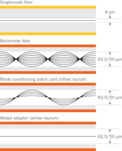
The key to the longer reach of the 10GBase-LRM standards on conventional multimode fibers is the use of a sophisticated signal processing technology in the receiver portion of these devices, referred to as electronic dispersion compensation (EDC). To achieve the maximum distance of 220 meters at 10 Gbits/sec, 10GBase-LRM transceivers have to be used with mode conditioning patch cables at both ends of the fiber link. Indeed, the standard relies on specific launch conditions. The mode conditioning patch cord is a specialized assembly that precisely offsets the SMF centerline with the MMF centerline. It is referred to as the “offset launch” technique. Therefore, the mode conditioning patch cord partially controls the light launch location of the SMF from the LRM singlemode source into the MMF.
By reducing the number of modes excited by this offset launching technique, the impact of modal dispersion is reduced in terms of differential mode delay and intersymbol interference, thereby allowing the maximum distance over OM1/OM2 to be increased to 220 m at 10 Gbits/sec. Nevertheless, be careful using this because there is no fiber or connector specification that ensures a minimum bandwidth level for this launch condition. Thus, depending on the quality of the optical cable and the eccentricity of field connectors, it is a hit-or-miss situation, leaving the user to experiment the efficiency on-site with their own fibers. Furthermore, the maximum distance of 220 meters supported by 10GBase-LRM equipment is unfortunately often too short for LAN backbone cabling networks, for which you can easily find links longer than that.But following this principle used in the IEEE study, the best-case scenario would be performing a mode conditioner, enabling a launch condition that accurately excites the fundamental center mode into the MMF core. In this way, the light transmission within the MMF would no longer induce modal dispersion, as only one mode would propagate—a kind of quasi-singlemode transmission over the MMF. Be assured, technologies have evolved and it is now possible to do so.
One way to overcome modal dispersion is to carry the information in just one mode over MMFs. By properly exciting a single fiber spatial mode, the coupling of the signal to different group modes, and thus of different propagation speeds, is negligible. The spatial mode can then be used as an independent high-speed transmission channel with the same transmission properties as a SMF. Today there are technologies that enable flexible and complete light shaping through a succession of transverse phase profiles similar to very complex optical lenses. Such technologies shape a laser beam from a transceiver in such a way that each mode within the MMF can be independently and precisely excited. This kind of technology is used as a way to increase the transmission capacity of existing MMFs by performing center launching on legacy MMFs. By overcoming speed and distance limitations, bit rates like 100 Gbits/sec can be carried over an existing multimode infrastructure of up to several kilometers or miles.
New technologies, new solutions
Solutions available today have adapted to different topologies, which allow for a progressive and flexible evolution of the legacy network optical communications, compatible with any type of 62.5/125 µm or 50/125 µm MMF (i.e. OM1 to OM5 fibers). The user simply places boxes between the active layer and the fiber. This technology consists solely of optical elements, so the solutions are passive, meaning they consume no energy and require no supervision. They operate at the level of the physical layer, which makes them transparent to the communication protocol and modulation format being used. There is no need for EDC or complex digital processing at the reception of the transmission; simple detection systems such as direct detection, implemented in a standard transceiver, is sufficient.
This technique is transparent to wavelength and can operate in the O-band (1300-nm window) or C-band (1500-nm window) range with standard singlemode transceivers from 1 to 100 Gbits/sec, or even higher. Intrinsic loss of such a modal adapter is less than 2 dB, and there is no transmission power penalty. In terms of link distance, a reach of up to 10 km covers the requirements for all types of LANs with legacy MMFs that would otherwise require a cabling infrastructure upgrade. If needed, it also makes MMFs compatible with singlemode wavelength division multiplexing (WDM) technologies, enabling a gradual and flexible increase in network capacity toward very-high-speed broadband, and thereby ensuring a durable cabling infrastructure.
With all that said, note that this type of technology can only shape a singlemode laser beam. It is therefor necessary to use singlemode transceivers. This, however, is not a significant economic issue. While it is true that singlemode transceivers are more expensive than multimode transceivers, at 10 or 40 Gbits/sec, the price differences are far less significant than they are at speeds above 100 Gbits/sec. We already have seen a significantly declined cost of 10- or 40-Gbit/sec optics due to technological advances at high-volume production. And finally, this new approach overcomes operational constraints. The cost savings achieved by avoiding complex recabling far outweigh the slight cost overhead for singlemode transceivers rather than multimode transceivers in your LAN.
In conclusion, today the limited capacity of LAN cabling infrastructure is a prevalent issue and complex wiring cases are not uncommon. The modal-adapting passive technological approach described in this article already has proven its effectiveness across numerous industrial, military, university and hospital campuses around the world. As a complement to traditional cabling, this new approach to transform MMF into SMF makes it possible to recycle the existing cabling infrastructure, one more step toward green IT, with proven benefits for end customers and ICT professionals.
Kevin Lenglé, Ph.D. is product line manager for the AROONA product line at CAIlabs.


