Optical fibers and cables are tested during production. They undergo a series of rigorous tests defined by the ITU-T G.650 or EN 188 000 standards. These include geometrical, mechanical, optical, and transmission tests. Transmission tests are the most important tests for us because we conduct them before and after the installation of cables.
All optical networks require testing before activation, and it is a very important and unavoidable step for the successful operation of the system. Generally, there are pre-installation and post-installation tests.
Pre-installation testing refers to tests that include checking cables and equipment before installation. This allows us to ensure that we have received the correct cables and equipment and that we are confident in their proper functioning. Today, the cost of optical cable and equipment installation is extremely high. Installing non-functional cables and/or equipment would be a significant problem. In addition to visual inspection, the use of appropriate measuring instruments such as VFL, test source (TS), optical power meter (OPM), OTDR, and others is required.
These are mostly standard measurement methods that are well-known to everyone. VFL checks fiber continuity, OTDR checks attenuation, reflections, or even possible fiber breaks. TS and OPM with reference cables are used for testing the attenuation of optical cables, connectors and splitters, and only the OPM is used for measuring the output optical power on active equipment (e.g. OLT and ONT).
After installing cables and equipment, we must test the entire network. FTTH PON networks have numerous specific features compared to other optical networks. These networks are very complex to test because they include optical splitters, WDM components (mux/demux), short links, multiple different wavelengths, optical connectors, and bidirectional communication.
Checking and Cleaning Optical Connectors
As we know, dirt is everywhere. Because of that, there’s a high chance that dirt will come into contact with connectors. If dirt gets on the surface of the connector (ferrule), attenuation and reflection can occur. Sometimes, this can lead to a complete interruption of service or even damage to the connector’s surface. Damage to connectors is a significant issue, especially if damaged connectors appear in instruments (e.g., OPM and OTDR) or active equipment (e.g. OLT and ONT). And the problems don’t stop there. Contaminants on the connectors can also cause BIP errors (Bit-Interleaved Parity) and irregular operation of ONTs (rogue ONT).
Fig. 1 – Different types of contamination on the surface of optical connectors
Therefore, checking the surface of the connectors using optical microscopes is required. It is the first and most fundamental step for any optical network. Today, many modern digital microscopes allow for simple, fast, and high-quality inspection of the connector surface. According to the IEC61300-3-35 standard, microscopes automatically inspect four zones for the amount and surface area of contamination and/or damage, and they provide a report on whether cleaning is necessary (as we can see in the next figure).
Fig. 2 – Example of a modern digital optical microscope
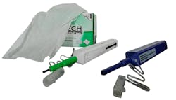
If there are contaminants on the surface of optical connectors, we must clean them. There are three main methods for cleaning fibers and connectors: wet, dry, and wet-dry methods. Today, the dry method with one-click cleaners is very popular. It is a simple, fast, and effective way to clean optical connectors.
Fig. 3 – Wipes and two types of one-click cleaners
It is very important to note that cleaning connectors is not allowed when the fibers are under high optical power, as this can lead to melting of the cleaner and permanent damage to the ferrule.
IL Testing
After the construction of an FTTH PON network, we must measure loss. For this measurement, technicians use a TS, OPM, and reference cables, or only an OLTS (Optical Loss Test Set) instrument with reference cables.
Fig. 4 – Selective power meter (left) and broadband optical power meter (right)
Measurements are taken at the wavelengths where the system will operate, based on the PON standard. For instance, in the case of the GPON standard, measurements are conducted at 1310 nm in the upstream direction and 1490 nm in the downstream direction. Due to the small difference in attenuation, measurements can also be taken at 1550 nm (the more common wavelength for test sources) instead of 1490 nm.
When the OLT is activated, technicians can use only PON meters to test optical power and measure losses. The OLT serves as the test source.
OTDR Testing
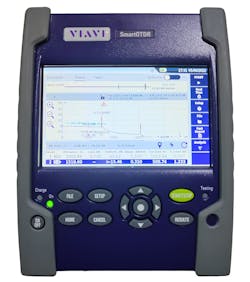
OTDR testing of FTTH PON networks is very complicated due to short links and optical splitters. Because the links are so short, the OTDR must have a high resolution. Short pulses are used to detect all events.
Fig. 5 – Example of an OTDR
In the downstream direction, FTTH PON has a P2MP topology, while in the upstream direction, it follows a P2P topology. Splitters introduce the largest attenuation in FTTH PON. By performing OTDR measurements in the downstream direction, we can observe a significant drop in optical power at that point. However, a new problem immediately arises. Splitters have at least two outgoing branches, which creates major challenges in the analysis. A problem with attenuation or reflection can occur on any branch, and technicians cannot see it precisely enough with this method.
Therefore, measurements in the upstream direction are also necessary. Only then can we clearly identify the problem in the network.
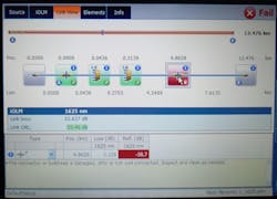
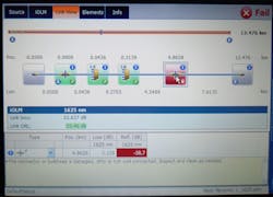
There are special instruments or OTDRs with specialized software that can be very helpful in these situations. These instruments can provide a complete overview of the network. Based on the attenuation and reflection at certain points, the instrument/software can identify splitters, connector pairs, fusion splices, etc., as we can see in the next figure.
Fig. 6 – OTDR with specialized software
Additionally, the instrument can highlight potential problems by coloring the problematic point and providing accompanying text.
Other Testing
In other tests, it is necessary to check passive components such as splitters and WDMs, as well as active equipment like OLTs.
Attenuation testing is required in both directions using appropriate wavelengths for splitters and WDM mux/demux. For this testing, a TS, OPM, and reference cables are used, similar to when testing cables or the entire network.
To measure optical power at the PON ports, an OLT uses a PON meter. The output optical power depends on the class of the SFP module. For example, in the case of the GPON standard, the B+, C+, and C++ classes of SFP optical modules are most commonly used.
About the Author

Vladimir Grozdanovic
Vladimir Grozdanovic is a graduate electrical engineer for telecommunications with more than 10 years of experience in access networks (HFC and FTTH) in large cable operators in Serbia (SBB and Jotel). He has many international certificates (FOA and Huawei) for optical networks. Vladimir is also the author of the book FTTx: Practical Guide for Designing, Building, and Maintaining FTTx Networks in Serbian. He frequently writes articles about optical networks for the Serbian magazine Glasnik and the American FOA Newsletter.
