Starting a cable test trail
Daniel E. Beougher, Tektronix Inc.
Problem
Defects found after fiber-optic cable is installed are expensive, time-consuming to find and labor-intensive to fix. How can you begin your test documentation to ensure that the cable was not faulty when it was delivered?
Solution
The installer should substantiate and document that the fiber-optic cable is free of defects before installation. To do this, you should perform a pre-installation test with an optical time- domain reflectometer, or OTDR, when the fiber-optic cable arrives from the vendor. This type of test is important because it quickly and easily determines product acceptance or rejection before installation. If you find any defects at this stage, you can return the cable to the vendor. Also, this documentation can be the start of your cable-test trail--showing that the cable was in acceptable condition before installation.
Procedure
1) Connect an OTDR to the free end of the fiber-optic cable while it is still on the reel. An OTDR will detect events on the fiber that cannot be detected visually. If the cable is already connectorized, this is easy. If not connectorized, use a bare fiber adapter to access the fiber end.
2) Check for correct cable distance, confirming fiber length and integrity. To check distance, an OTDR launches a laser-generated light pulse down the fiber at the transmission end of the cable. The OTDR measures the time taken by the light pulse to make the round trip on the fiber and calculates that time into distance. The instrument then detects the backscatter returned from the fiber and any reflections from shiny surfaces such as the end of a fiber or splices. Another important item to look for is unexpected changes in backscatter level caused by undocumented fusion splices, macrobends, microbends and material anomalies.
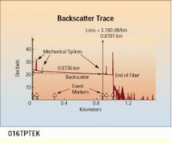
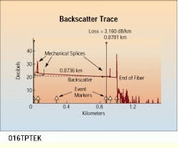
3) Next, test for fiber loss, which confirms the manufacturer`s specification. The backscatter trace is a representation of the fiber. The slope of the backscatter trace discloses that less and less light is being reflected back as the length of the fiber increases. This slope represents fiber loss. Typical fiber-loss measurements are given by the manufacturer as the amount of light in decibels lost per kilometer. For example, a multimode local area network fiber could lose 3 dB/km.
4) Store the test documentation on a floppy or hard-disk file and label all test results.
This optical time-domain reflectometer waveform shows the beginning of fiber, backscatter of fiber, mechanical and fusion splices, end of fiber, and loss and distance readings.
Daniel E. Beougher is training manager, cable network analysis products, at Tektronix Inc., Redmond, OR.

