Bandwidth and throughput capacity are all about a fiber’s ability to receive and transmit light paths.
by Valerie Maguire, Siemon
It may be surprising to learn that the idea of using lightwaves to transmit voice signals is well over a century old. In fact, Alexander Graham Bell’s “photophone” invention used a narrow beam of sunlight focused on a thin mirror that vibrated when hit by human sound waves to transmit voice signals over distances up to 700 feet back in 1880. The foundation for modern techniques of transmitting light energy was set in the 1960s when ruby lasers were first demonstrated, and in the 1970s when workers at Corning Glass Works produced the first optical fiber with signal losses less than 20 dB/km. Since then tremendous strides have been made in the refinement of semiconductor laser and light-emitting diode sources, as well as the optical fiber cables and components used to support the transmission of light energy.
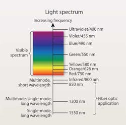
The common optical communications wavelengths of 850 to 1550 nm fall between the ultraviolet and microwave frequencies in the light spectrum.
While optical fiber cabling expertise is commonly thought to fall within the domain of service providers, it cannot be overlooked that optical fiber cabling plays an important role in supporting customer-owned telecommunications infrastructures as well. Beyond supporting long-length runs installed between buildings or points in a customer-owned campus environment (commonly referred to as “outside plant” cabling), it is interesting to note that on average, 20% of the cabling installed in the enterprise and 40% of the cabling installed in the data center is optical fiber cabling. While balanced twisted-pair copper cabling may still be the media of choice due to familiarity, perceived ease-of-termination compared to optical connections, and significant lower local area network (LAN) equipment costs, the following benefits are compelling reasons to consider optical fiber cabling in your information technology (IT) infrastructure.
- Extended distance support beyond the balanced twisted-pair limit of 100 meters
- Smaller media (e.g. two Category 6A cables occupy the same space as one 216-fiber cable.)
- Lighter media (e.g. 108 Category 6A cables weighing 1,000 pounds or 1 216-fiber cable weighing 40 pounds can be used to support 108 channels that are 200 feet in length.)
- Significantly higher port density in the telecommunications room and line-card density in the data center (up to 1,728 in a 4U housing)
- Smaller pathways
- Improved air flow due to less cable damming
- Media robustness; optical fiber can withstand double the pull tension (50 lb versus 25 lb) of balanced twisted-pair cabling
- Reduced LAN equipment power consumption and cooling costs
- High-speed applications support; 40- and 100-Gbit/sec optical-fiber Ethernet applications will soon be published by the IEEE 802.3ba Ethernet Task Force
- Centralized optical cabling may be used when deploying centralized equipment in the horizontal to eliminate the need for an optical crossconnect
- Immunity to electromagnetic and radio frequency interference (EMI/RFI)
- Immunity to lightning strikes
Signal transmission over optical fiber cabling
Optical communication is the transmission of photon (or light) energy through a low-loss waveguide whose function is to propagate the light signals over long distances. In telecommunications systems, the source of the photon energy may be a light-emitting or semiconductor laser diode, whose function is to produce light energy at a single wavelength. By turning the light source on and off quickly, streams of ones and zeros can be transmitted to form a digital communications channel. LED and laser light sources vary considerably with respect to their cost, transmit speed, and physical properties.
The wavelength of the optical light source describes the frequency of the transmitted lightwave (the longer the wavelength, the lower the lightwave’s frequency) and has been selected to best match the transmission properties of recognized optical fiber types. A helpful analogy is to think of “wavelength” as the color of the light signal that is being transmitted. The common optical communications wavelengths of 850 nm to 1550 nm fall between the ultraviolet and microwave frequencies in the light spectrum.
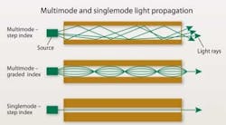
Step index multimode fibers (top) have a uniform refractive index, meaning all energized light paths travel at the same speed whether they’re propagating at the fiber’s core or edge. In graded index multimode fibers (middle), the refractive index gradually changes from a maximum at the center to a minimum near the edge, which minimizes undesirable modal dispersion. Virtually all multimode fibers made today are graded-index.
“Source aperture” describes the width of the transmitted light signal pulse. This characteristic is also related to the diameter of the optical fiber (the “waveguide”) that will optimally transmit the light pulses, which helps to explain why there are several types of optical fiber cabling systems available. Large diameter optical fiber (50- and 62.5-µm) is required to adequately support transmission of light sources with larger apertures such as LEDs and vertical-cavity surface-emitting lasers (VCSELs) by minimizing signal loss and maximizing transmit distances. Small diameter optical fiber (e.g. 9-µm) is required to adequately support transmission of laser light sources.
As a result of the variance in source aperture and optical fiber size, there are two ways that light can propagate through optical fiber. Because 62.5- and 50-µm optical fiber diameters are relatively large compared to the wavelength of the transmitted light signal, there are many paths or “modes” that light energy may take when it propagates through the optical fiber. This type of transmission is referred to as multimode. Because the 9-µm optical fiber diameter is similar to the wavelength of the transmitted light signal, only the one wavelength associated with transmission propagates through the optical fiber. This type of transmission is referred to as singlemode.
Index of refraction
Careful examination of multimode signal propagation quickly raises a concern about how the design of the optical fiber itself may adversely impact signal propagation. The earliest optical fiber design, referred to as step index, was constructed with a uniform index of refraction. This meant that all energized paths of light, whether propagating at the core or at the edge of the optical fiber, traveled at the same speed. The undesired result is that, over distance, the energized modes in a step index optical fiber will support different path lengths and the output pulse will subsequently have lower amplitude and wider spread (longer duration) than the input pulse due to the faster and slower light paths. Modal dispersion describes the degree to which the output pulse has spread compared to the input pulse and effectively limits the bit rate or bandwidth of the step index optical fiber to between 20 and 30 million signal cycles per second transmitted over the distance of one kilometer. This bandwidth capacity is typically presented as 20 MHz∙km to 30 MHz∙km.
To compensate for this phenomenon, graded index optical fiber is constructed so that the index of refraction gradually changes from a maximum at the center (“slowing” the light signal) to a minimum near the edge (“speeding up” the light signal) of the optical fiber. This increases the bandwidth of graded-index fiber to greater than 1 billion signal cycles per second transmitted over the distance of one kilometer—1 GHz∙km. Virtually all multimode fibers manufactured today are graded-index. Because singlemode optical fiber supports only one wavelength of light, modal dispersion is not a concern for this medium.
An additional improvement to multimode optical fiber design involves optimizing the media to specifically support the VCSEL light source. Because the source aperture of an LED source exceeds the diameter of the largest optical fiber suitable for telecommunications (62.5 µm), all modes of a multimode fiber are energized and the pulse output is fairly easy to control with graded index optical fiber. However, because the source aperture of a VCSEL light source is much less than the diameter of the smallest optical fiber suitable for telecommunications (50 µm), only a portion of the available transmission paths in a multimode fiber are energized. Second-generation “laser-optimized” graded-index optical fiber is even more tightly specified to ensure that the pulse output of a VCSEL source exhibits well-controlled and limited modal dispersion.
In consideration of next-generation applications that will employ more-complex transmission schemes such as transmitting more than one wavelength over a single fiber (e.g. wavelength division multiplexing), emphasis is being placed on ensuring that optical fibers have a smooth attenuation profile over the range of possible transmission wavelengths. Of particular concern is attenuation increase in the 1360- to 1480-nm range (also known as the “E-Band”or “water peak” range) due to hydroxyl ions that are absorbed into singlemode fibers during the manufacturing process. Low water peak (LWP) singlemode fibers have undergone an additional manufacturing step to reverse the water absorption and have a nearly smooth attenuation profile. Zero water peak (ZWP) singlemode fibers undergo a more-complex process that eliminates all losses in the water peak range and further lowers attenuation loss across the entire spectrum.
The many variables associated with optical fiber transmission, including the capabilities of the light source, modal dispersion, chromatic dispersion (a second order effect characterizing slight shifts in the transmit light spectrum), bandwidth, and losses in the transmission line contribute to the bit rate and distance capabilities of various optical fiber media. In general, lasers transmitting over singlemode fiber support the highest bandwidth and longest distance, while LEDs transmitting over larger diameter (62.5-µm) multimode fiber support the lowest bandwidth and shortest distances.
Editor’s note: This is part one of a two-part article on the fundamentals of optical-fiber cabling and transmission. Part two, which will appear in our next issue, will cover cable construction, connectivity options, and field deployment.
Valerie Maguire is global sales engineer with Siemon (www.siemon.com).

