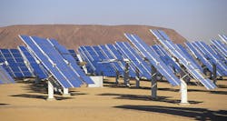
Fiber's characteristic immunity to electrical interference and long-distance capability make it an essential part of a solar farm.
By Martyn Easton, Corning Cable Systems
Utility-scale solar "farms" require a distributed control network to monitor and control the production, aggregation and flow of electrical energy from the photovoltaic arrays onto the grid. An optical-fiber network is useful for this purpose for the prime reasons of low loss/long reach as well as immunity to electrical interference, ground loops and lightning.
A general issue with electrical power is that it is difficult to store in large quantity. The electrical grid connects consumers with generating plants, and consumption must match production. Any significant imbalance could cause grid instability or severe voltage fluctuations, and cause failures within the grid. In extremes, rolling blackouts or brownouts are used to reduce the load. Solar is an appealing source in that it is abundant and clean with virtually no variable cost of production. However, the output of an array is dependent on time of day, time of year and the weather. Further, photovoltaic (PV) panels generate direct current (DC), which must be converted to alternating current (AC) and matched to the voltage, frequency and phase of the power on the grid. Hence, it is critical to monitor, control and report the flow of solar energy onto the grid in real time.
Right sizing
A commercial PV panel is approximately 1 to 2 square meters in size and produces a maximum output of 125 to 150 W/m2. Hence, a utility-scale solar plant requires a large area of panels—i.e., 1 MW of output requires 4,000 to 8,000 panels with a surface area of 8,000 m2. With necessary spacing to enable access for panel maintenance, the deployment area is on the order of 30,000 m2, which is about the area of four soccer fields per one MW of output. Current utility-scale solar plants range in size from 30 MW to more than 200 MW. Larger projects in planning and construction range up to 1,000 MW.
Whether smaller or larger, these plants are spread over a very large area of land. The topology of the site has an important bearing on how the PV arrays are laid out. All the panels need to be connected with power cables, so undulations, water courses and other features will have an important bearing on cable routes. A key limiting factor in the system design is the necessity to convert the DC output of the arrays into AC power, conditioned for integration onto the grid. Inverters perform this function and are currently rated for 1 to 1.25 MW. This means that arrays are connected in 1-MW blocks to an inverter at a power converter station (PCS). These converter stations then need to be connected and aggregated at a photovoltaic combining switchgear (PVCS) location. The PVCS locations will connect to a solar plant substation having all the equipment and functions of a transmission substation, and finally the interconnect onto the grid.
Fiber applications
As mentioned earlier, real-time monitoring and control of the power generation is critical. As such, a Supervisory Control And Data Acquisition (SCADA) network is deployed to the site, substation and all PVCS/PCS locations from a site control center (SCC). Optical-fiber cabling is ideal to provide this connectivity. With a signal attenuation of <0.4 dB/km, the reach of a cable is not limiting in any size of a deployment. Better still, the inherent dielectric nature of glass optical fiber and cable means no signal interference, equipment damage or safety concerns when running amidst high-voltage power cables collecting and aggregating the solar power. A typical deployment scenario is to run fiber rings from the SCC through the PVCS locations, and from the PVCS to the PCS locations.
In addition to the SCADA network, other applications may be deployed over the same fiber infrastructure; surveillance cameras can be a useful addition for the site operator to be able to see visually what is going on before dispatching a technician and vehicle to investigate.
Fiber count and type
Sizing the fiber plant, the number and type of fibers is an important decision because it is expensive and disruptive to add capacity at a later time. The ring architecture is used to provide fault tolerance and redundancy with fibers coming in to feed each location from two directions. Bandwidth demands are not high in these applications, but the reach for a link can be several kilometers in length. As such, standard G.652 singlemode is the fiber type of choice.
With regard to fiber count, commonly 12 fibers are provisioned from the SCC to each of the PVCS sites. In the illustration, this would entail running a 48-fiber cable through the three PVCS sites, dropping 12 fibers at each and 12 fibers at the substation site. Six-fiber cables are typically run from PCS-to-PCS. This provides four fibers for two control circuits, plus two spares. However, if video surveillance or other applications are required, 12 fibers may be more appropriate.
Cable choice
Solar farms present a very typical outside-plant cabling environment. They are most usually located in dry, sunny areas where high temperatures may be anticipated. But clear skies can also produce very cold night-time temperatures, and a large daily swing between the two extremes. Water should not be overlooked in any outdoor application.
A particular hazard in a solar farm is the basic fact that there are power cables everywhere. As a general practice, all-dielectric fiber cable constructions are desirable to eliminate grounding and coupling concerns. In many cases, the simplest approach is to direct-bury the cables, often alongside the power cables. This requires a cable designed for the purpose with adequate crush resistance and rodent resistance. Corrugated steel tape armoring is the usual answer and can be used with appropriate grounding of the armor, but this goes against the desire for an all-dielectric solution. Double-jacketed dielectric cables with fiberglass armoring also are available.
Either way, a standard loose-tube construction is most appropriate to protect the fibers from the environment. In some cases, the site topology may not allow for direct-buried cables, and some aerial runs are required. In this case, all-dielectric self-supporting cables are used. For the lower-fiber-count cables between PCS sites, a more-compact central tube drop cable may be considered. Field-termination procedures are slightly different, but it will offer the same level of robust protection for the fibers.
Termination options
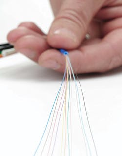
Industry-standard techniques are used for the termination of the cables and depend somewhat on the capabilities of the installer. Common options are fusion splicing or no-epoxy/no-polish (NENP) connectors. NENP connectors are field-terminated on the fibers after a buffer-tube fanout kit is installed. It is a quick and reliable choice, especially for the low-fiber-count cables at the PCS sites. The connectors can be easily installed in confined spaces with simple hand tools in less than two minutes. And they are tested to be highly reliable and stable across the wide temperature range of an outside installation.
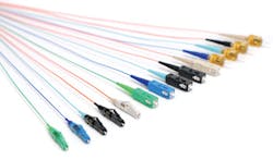
The choice of connector type, whether spliced pigtails or field-installable connectors, presents some options. A good practice is to standardize on one type for all cable terminations and to make this choice match the predominant connector interface required for the network electronics. This likely will result in the SC or LC type. Both are push-pull connectors widely used in the industry. The LC is smaller and offers higher connector density. This is rarely a limiting factor in a solar application, but the LC is increasingly the interface on the electronics.
The choice of termination housing to store, manage and protect the connectors is important. The main issue is exposure to the elements. The PCS and PVCS gear may be pad-mounted and provide no protection. In this case, a fully weatherproofed, sealed, surface-mount enclosure is appropriate to keep out dust, dirt and water. At the site control center, and likely at the substation, indoor rack-mount termination housings are appropriate.
The overall design and layout of the cabling infrastructure will be site-specific. But some standard practices apply, including the following.
- Size the fiber plant to accommodate current and future known applications. Then add some capacity for unknown additions. It is much easier to add it up front.
- Consider the site topology and obstacles to select a cable type that will provide lasting protection for the fibers in all likely and unlikely conditions.
- Build redundancy and fault tolerance into the system. Expect the unexpected.
- Consider the prospects for growth and needs due to site expansion. Many sites are built out in successive phases.
- Most cabling problems, short of the back hoe, usually occur at the cable ends. Select appropriate termination enclosures that will adequately organize and protect the fiber terminations.
Optical-fiber cabling continues to be deployed, and is operating reliably, in many utility-scale solar arrays all over the world. ::
Martyn Easton is global marketing manager with Corning Cable Systems (www.corning.com/cablesystems).


