Generally, FTTH passive optical network(s) (PON) are built to a length of up to 20 km. Optical fibers are split using symmetrical splitters (32, 64, or 128 splits), with one, two, or rarely three levels of splitting. Networks are constructed either underground (preferred) or above ground (common in countries with weaker economies), using standard fiber connection methods — fusion splicing or pre-connectorized solutions, typically applied only in the final segment (drop segment). However, these are standard solutions for urban and suburban areas.
What are the possible FTTH PON solutions for rural areas?
Standard construction method
Operators rarely build FTTH PON networks extending beyond 20 km using standard symmetrical splitters with one or two splitting levels. In such cases, they are limited by the optical budget and must reduce the number of fiber splits to 16 (e.g., first splitter 1:2, then the last splitter 1:8) or 8 (e.g., first splitter 1:2, then the last splitter 1:4). They often operate at the limits of the optical budget, which can later result in problems that are extremely difficult to resolve.
Additionally, feeder cables with a higher number of fibers are required due to the lower level of fiber splitting. In some cases, this requires the installation of new cables or the reconstruction of the network (e.g., when CATV companies switch from 2 fibers to 1 fiber for optical nodes), which can pose a significant challenge.
However, due to the mentioned issues, most telecommunications companies avoid building standard FTTH PON networks. Instead, they choose remote optical line terminal (OLT) solutions and/or utilize asymmetric splitters or taps in combination with standard optical splitters. In addition, pre-connectorized solutions are being introduced.
Remote Optical Line Terminal (OLT)
Telecommunications companies predominantly prefer this solution. The existing or newly installed feeder cable is routed to the rural area where the network will be deployed. The cable can be laid either underground or above ground, utilizing various installation techniques. The number of fibers in the feeder cable can be significantly lower than in standard feeder cables. Generally, a cable containing 12, 24, or at most 48 fibers is sufficient, allowing for the connection of several mini OLTs, with additional fiber capacity reserved.
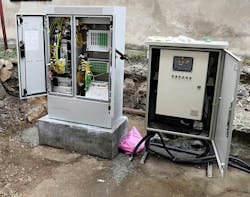
A mini OLT can be either an outdoor OLT or an indoor device with a suitable cabinet.
Both outdoor OLTs and indoor OLT cabinets must provide high protection against water and moisture, typically rated IP68. Additionally, OLTs require a stable power supply, backup batteries or UPS (to ensure a minimum of 8 hours of operation without standard power), proper grounding, ventilation, etc.
Fig. 1. An example of a remote OLT
The use of Uninterruptible Power Supply (UPS) units or batteries requires regular performance checks. Additionally, a constant power supply, whether from permanent or mobile generators, is essential. Ensuring the physical protection of this equipment remains an ongoing challenge, with various solutions being implemented, such as the installation of cameras, alarms, secure physical spaces, and other similar measures.
Mini OLTs typically have 4, 8, or a maximum of 16 PON ports. Most commonly, they support Gigabit Passive Optical Network (GPON), XG(S)-PON, or even both GPON and XG(S)-PON standards simultaneously. This allows for the construction of a standard FTTH PON network, enabling the development of a network up to 20 km long with symmetrical optical splitters, typically divided into up to 128 fibers across 2 or 3 splitting levels.
What is the new challenge?
We are limited by the small number of PON ports, and the irregular, scattered arrangement of houses makes traditional construction with symmetric splitters an inefficient solution. For this reason, asymmetric splitters or taps are introduced and used in combination with symmetric splitters (cascade solution).
Using solution with taps and symmetrical splitters
This solution enables optimal FTTH PON construction in rural areas. In the first level of splitting, an asymmetric splitter is used, typically with a 30/70 ratio, followed by a symmetrical splitter in the second and usually final level of splitting, typically 1:8. These splitters send 70% of the power further along the optical line, while 30% of the optical power is sent to a symmetrical splitter for subscriber connection. The use of taps significantly reduces the number of required cables and fibers.
Pre-connectorized solutions
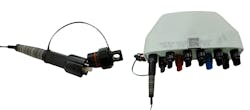
Pre-connectorized solutions have become increasingly popular, particularly for the drop segment, and in recent years, they have also been adopted for other segments of the PON network (ODN gen. 2). Today, it is possible to build an entire network without the need for fusion splicing. Typically, cables with a small number of fibers are used.
Feeder cables usually contain a maximum of 12 fibers with MPO/MTP connectors, distribution cables have 1 or 2 fibers with SC/APC connectors, and drop cables contain 1 fiber with SC/APC connectors. All connectors are designed to protect against water and moisture penetration, typically with an IP68 rating.
Fig. 2. Examples of pre-connectorized solutions
In addition to pre-connectorized cables, specially designed optical distribution boxes are used, which do not require opening but only the physical connection of connectors. Thanks to this solution, network construction time is significantly reduced, and reliability is improved, as there is no need for fusion splicing or opening distribution boxes. Furthermore, maintaining such a network does not require trained personnel or expensive tools for processing and fusion splicing.
Conclusion
The use of mini OLTs with pre-connectorized cables and specially designed enclosures featuring both asymmetric and symmetric splitters enables optimal network construction in rural areas. This approach results in a high-quality, reliable network that allows for easy subscriber connections and simple maintenance.
About the Author

Vladimir Grozdanovic
Vladimir Grozdanovic is a graduate electrical engineer for telecommunications with more than 10 years of experience in access networks (HFC and FTTH) in large cable operators in Serbia (SBB and Jotel). He has many international certificates (FOA and Huawei) for optical networks. Vladimir is also the author of the book FTTx: Practical Guide for Designing, Building, and Maintaining FTTx Networks in Serbian. He frequently writes articles about optical networks for the Serbian magazine Glasnik and the American FOA Newsletter.


