By Eric R. Pearson, CFOS/T/C/S/I, Pearson Technologies Inc.
Over the past 31 years, this author has been active in fiber-optic communications. During that time, there have been many significant changes in technology. Here’s a sample of them.
- Transition from a multimode-dominant market to singlemode’s increased deployment
- Attenuation rates from 6 dB/km to below 0.19 dB/km
- Data rates from 10 Mbits/sec to 400 Gbits/sec
- Optical transmission from a few kilometers to 7000 km
- Fiber transmission of a single wavelength to 128 simultaneous wavelengths
- Optical time-domain reflectometers (OTDRs) with boxcar averagers and manual measurement, to sophisticated CPU-controlled equipment providing automatic trace analysis and generating link maps
- Fibers from bend-sensitive to bend-insensitive
Attenuation rate testing
While the industry has justifiably regarded the development of bend-insensitive OM3 fibers as an advancement, there has been at least one unexpected consequence. We have observed unusual, high multimode OTDR attenuation rates (hereafter “rates”), in both bend-insensitive fibers and bend-insensitive cables.
These high rates can result in rejection of properly installed cables due to excessive attenuation rates, misinterpretation of rate values, and improper interpretation of such rates during troubleshooting activities. These high rates can result in misinterpretation of OTDR data from data centers, as data centers have relatively short fiber lengths, in which these increased rates occur.
The OTDR test results from some multimode fibers have indicated increased rates at the fiber ends near the OTDR. These increases are not due to high connector reflectance. Nor are they unique to a single fiber; we observed them in multiple fibers and cables. These increased rates are not due to OTDR noise, as test conditions chosen to reduce noise did not eliminate the increases. Finally, these increased rates are not unique to an OTDR, as we observed these increases with three different OTDRs.
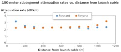
These increased rates appear as a transient effect that decreases with increasing distance from the OTDR. A quick review of a trace may not indicate this increase, as it can be subtle.
When we tested fiber sections, which exhibited increased forward-direction rates, in the reverse direction, these increases disappeared. Note that the rate exceeds the specification, 3 dB/km at 100 meters in the forward direction and at 1100 meters, which was 100 meters from the launch cable, in the reverse direction.
Not all bend-insensitive multimode fibers exhibit increased attenuation rates at the end near the OTDR. In addition, as the length of the launch cable increased, the increases in rate decreased. Thus, the rates of the fibers are dependent on the distance of the fiber segments from the OTDR.
This is an undesirable situation, because tests of the same fiber, conducted at different times with different-length launch cables, result in different attenuationrates.Consequences of inconsistencies
There are two consequences of using the rate values determined by the OTDR software. First, after initial installation, increased attenuation rate can result in improper rejection of the cable due to that rate exceeding the maximum specification. Second, during troubleshooting, this increased attenuation rate can be misinterpreted as indicating improper installation, damaged cable, or degraded cable.
We make the following observations.
- Manual measurements of the OTDR rate tend to result in increased attenuation rate values.
- When the segment length is longer than the length exhibiting increased rates—approximately 100 meters—the automatic trace analysis software tends to reduce the rate increase. This reduction is a result of the use of the least-squares analysis (LSA) method, (a.k.a. best fit method) for determining attenuation rate. The LSA method tends to distribute the rate in the section of increase over the entire fiber length.
- The increased rate occurs at multiple pulse-width and time settings.
- We have not observed this behavior on OM1 or OM2 fibers. Nor have we investigated this behavior on singlemode fibers.
- Because fibers with and without this increase have approximately the same reflectance, connector reflectance is not believed to be the cause of increased rates.
- As increased rates are an artifact of OTDR testing, such rates do not indicate excessive power loss.
Some bend-insensitive multimode fibers exhibit increased OTDR attenuation rates due to a transient condition at the end of the fiber near the OTDR. This condition is an artifact of OTDR testing, not a characteristic of the fiber. Such increased rates can complicate link certification or troubleshooting.u
Eric R. Pearson, CFOS/T/C/S/I is principal of Pearson Technologies Inc.


