Implementing a centralized optical-fiber cabling system
Todd Harpel,
Hubbell Premise Wiring Inc.
Problem
As fiber becomes more popular for horizontal cabling, cabling installers and cable-plant managers are centralizing the electronics that supports users on multiple floors. The problem is to create a centralized optical-fiber cabling system using 62.5/125-micron multimode fiber that is standards-compliant and will support future multigigabit services.
Solution
According to TIA`s TSB-72, centralized optical-fiber cabling can be implemented by providing a direct connection from work areas on each floor to the centralized (or main) crossconnect.
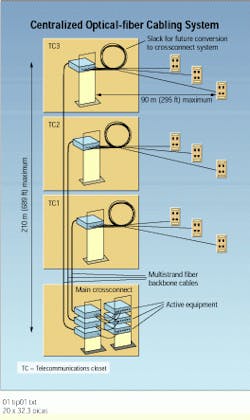
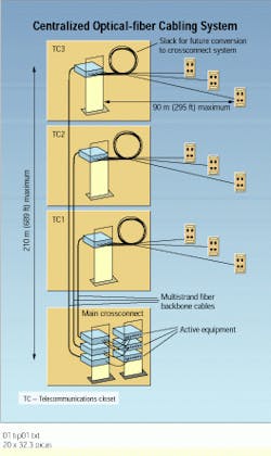
The maximum horizontal cabling distance from the telecommunications closet (TC) to the work area remains 90 meters (295 feet). The combined length of the horizontal and intrabuilding backbone cable, as well as the patch cords, however, can extend to 300 meters (984 ft). Enough slack must be left conversion to standard star-wired horizontal and backbone systems. The TSB permits three methods for implementing this centralized system. Of these, the interconnect method allows the greatest flexibility to ease future conversion.
Procedure
Pull the horizontal cabling to each work area from a TC on the same floor following the procedures in Section 4 of tia/eia-568a.
1) Terminate each end of the horizontal cable with ST or SC connectors.
2) Mount a patch panel in the TC in a way that will allow an additional patch panel to easily be added adjacent to it at a later date without disturbing other cabling.
3) Connect the TC end of the horizontal cable to the front or user side of the patch panel, ensuring that the correct bend radius is maintained and proper strain relief is provided.
4) Leave enough cable slack in the horizontal cables to allow them to be disconnected from this patch panel and plugged into the back or technician`s side of a new patch panel.
5) Install a 62.5/125-micron multimode optical-fiber backbone cable from each TC to the main crossconnect, following the procedures in Section 5 of tia/eia-568a.
6) The backbone cable to each TC must contain enough strands to provide each work area terminating in that closet with two strands, as well as additional strands for future growth.
7) Terminate each strand in the backbone cable with ST or SC connectors.
8) Connect the TC ends to the back of the patch panel where the horizontal cables are connected in each TC.
9) Connect the other ends of each backbone cable to the back or technician`s side of patch panels in the central crossconnect.
10) Label the ports of the patch panels in the central cross connect with the station number and floor according to the procedures outlined in tia/eia-606.
TIA`s TSB-72 specifies both the horizontal and backbone lengths for a centralized optical-fiber cabling system.
Todd Harpel, rcdd, is technical services manager at Hubbell Premise Wiring Inc. (Stonington, CT).

