Following some best practices when installing cable tray can pay dividends in cabling system electromagnetic compatibility performance.
The International Electrotechnical Commission (IEC; www.iec.ch) defines electromagnetic compatibility (EMC) as the ability of a device, equipment, or system to function satisfactorily in its electromagnetic environment without introducing intolerable electromagnetic disturbances to anything in that environment. For professionals in the field of designing, specifying, installing, and using structured cabling systems, EMC in the data room is of significant concern. In this article, we will discuss the role that metal cable tray plays as a contributor to EMC performance within structured cabling systems.
In the data room, the metal cable tray is part of the electrical structure, and also part of the metallic structure. Any metallic structure is known as a generalized shield, meaning it reduces voltage differences between metal structures in case of common mode disturbances.
Importantly, a metal cable tray does not have to enclose the cable in order to function as a generalized shield. Any continuous metal along the cable is a shield. In fact, any metal structure that is continuous and parallel along the cable patch can be considered a shield.
As a shield, the metal cable tray is subject to bonding and grounding requirements. And what has been said very often about shielded cable is also true of a metal cable-tray system. When properly bonded and grounded, the system improves EMC performance. When poorly bonded and grounded, it degrades—and potentially significantly degrades—EMC performance.
Good engineering practice
In July 2007, the European Union introduced an EMC directive stating, in part, that in any electrical installation, the installer must document that the EMC performance of the complete installation is made according to good engineering practice. But what is good engineering practice? We will conclude this article with some best-practice steps that you can take to maximize EMC performance in your cabling systems that are conveyed through metal tray.
Several common EMC problems might be described as come-and-go. They can affect EMC performance for a brief time, and be either one-time events (like a lightning strike), or periodic disturbances (such as on/off transients or radio transmissions). Other EMC disturbances may be more steady and cause network slowdowns. That is, these disturbances may force packaged signals to be re-packaged and re-sent. Regular re-transmission of data packets lowers the network's actual throughput.
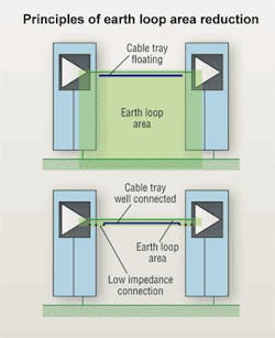
A metal tray that is not properly bonded to earth/ground at each end can result in an earth loop, frequently referred to as a ground loop. A simple definition of an earth loop, in this case, is an unwanted current that runs through the metal tray. In fact, an improperly bonded tray can be surrounded by a rather large earth-loop area. Designers, installers and users of cable tray systems should implement practices that will reduce the earth-loop area as much as possible.
While a floating cable tray—one that is not bonded at either end—can leave an earth-loop area that reaches data room's floor, a well-connected cable tray that includes low-impedance bonding connections at each end will significantly reduce the earth-loop area.
Test results revealed
Schneider Electric, parent company of Defem, conducted tests using Defem cable tray to determine the installation prac- tices that would yield the best EMC performance. Previous testing had shown that tray design had only a minor impact on EMC performance. So, whether a tray is wire-mesh, solid- metal, perforated-metal, or ladder-style, the tray does not affect EMC performance nearly as much as the installation practices used when putting the tray in place.
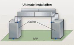
The recent testing determined what would be considered an ultimate installation method. In that ultimate method, the tray is directly connected to the top of an equipment cabinet on each end. In this case, as in all the cases that will be described here, the room's floor acts as the ground reference plane. While this type of continuous-tray installation is the best option from the standpoint of EMC performance, it is not realistic or practical to expect network design and installation professionals to build this type of system connecting two equipment cabinets.
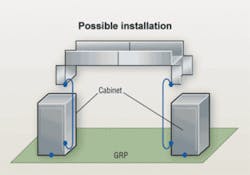
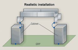
A more realistic installation method is to use a short ground wire to connect each end of the tray to the top of the cabinet below. Another possibility is to use a long ground wire at each end of the tray, connecting the tray to a low point on each cabinet. This setup, however, produced poor EMC results at certain frequencies up to 100 MHz. With every Ethernet networking protocol operating in that frequency range, a user is risking packet-busting EMC performance by deploying this physical setup.
Finally, the poorest performing installation method is to connect the tray once, with a single ground wire between the tray and the cabinet. Test results showed such a setup is worse than having no metal tray at all, and actually creates a disturbance to the data signals.
This testing showed that the most critical parameter in achieving good EMC performance when using metal cable trays is to maintain a connection between the trays and the cabinets, thus maintaining continuity of the generalized shield. The best-performing system, unrealistic as it might be, has the tray physically connected to the cabinets. A more realistic and very achievable setup includes short ground wires between the tray and cabinets. This scenario showed clear improvement over the other setups in which ground wires were used. Less desirable is a setup in which long ground wires are used to connect the tray to the cabinets. And, the most undesirable scenario is one in which a ground connection is made between the tray and a cabinet at just one end.
Returning now to the idea of good engineering practices, as required by the EU's EMC directive. IEC standards specify the use of gas-free and vibration-safe joinings of trays, to ensure a maximum 50-mO connection. Additionally, IEC specs call for the marking of tray joints to indicate they have been bonded to earth.
Additionally, based on the research and testing described in this article, we consider it good engineering practice to connect metal cable trays to all cabinets with ground wire, preferably at the cable entrance.
ED CRONIN, RCDD, is president of Cronin Consulting (www.croninconsulting.biz) and CLAES ROSENBERG is export manager for Defem Systems (www.defem.com), a Schneider Electric business.
Sun Microsystems claims data center efficiencies
Responding to market demand for more energy-efficient data centers, Sun Microsystems (www.sun.com) recently announced the completion of its Broomfield, CO data center. The largest data center consolidation project undertaken in the company's history, the Broomfield facility incorporates Sun's latest energy-efficient systems and expertise, including new data center design and power and cooling technologies. Sun estimates it will save more than $1 million in electricity costs and 11,000 metric tons of CO2 per year in Broomfield; the facility is also estimated to help Sun reduce its carbon footprint by 6% in the U.S. Sun also announced the availability of new data center efficiency services to help customers retrofit and build more efficient data centers like the company's Broomfield and Santa Clara data centers.
The Broomfield data center follows similar Sun projects completed in August 2007 in Blackwater, UK, Santa Clara, CA, and Bangalore, India. As in Santa Clara, Broomfield is based on Sun's Pod architecture, which delivers footprint compression while providing capacity for future growth.
The Broomfield data center showcases revolutionary data center design, with the latest in modularity, scalability and flexibility to drive incredible efficiencies in cost, electricity and overall carbon savings, says Dave Douglas, senior vice president of cloud computing and chief sustainability officer.
Separately, Sun was listed among the Uptime Institute's (www.uptimeinstitute.org) Global Green 100 for 2009. The Institute developed the list of global corporations it says have made significant energy-efficiency achievements operating major data centers.


