Bonding of ICT Infrastructure to Electrical Power Infrastructure
kW Mission Critical Engineering (kW MCE), a member of WSP, is one of the world’s leading engineering and professional services consulting firms. Our team of technical experts and strategic advisors has a deep and broad knowledge of planning, designing, and delivering data centers, specializing in hyperscale data centers, while offering clients integrated multidisciplinary solutions, including information and communications technology (ICT) design services.
Our ICT design engineering studio team members are often asked about ICT bonding design and installation best practices as they relate to industry standards. A primary driver of this client conversation involves a fundamental understanding of both electrical power bonding and grounding design and installation, and how the electrical bonding and grounding infrastructure interconnects to the ICT bonding infrastructure.
Industry standards-based design
In North America, the primary source of truth for ICT bonding design and installation best practices is ANSI/TIA-607-E-2024 Telecommunications Bonding and Grounding (Earthing) for Customer Premises. Published in May 2024, this American National Standards Institute (ANSI) industry standard has evolved over many years to accommodate emerging technologies. Dozens of organizations, including engineering design firms, manufacturing firms, Fortune 500 companies, electrical and ICT contractors, systems integrators, and others have supported its ongoing development. Members of the Telecommunications Industry Association (TIA) volunteer to create technical content and work towards achieving consensus, eventually leading to published standards. As such, this ICT bonding industry standard enjoys widespread acceptance, within the ICT industry. This ICT bonding standard has been written to harmonize with complementary TIA standards (e.g., TIA-568 series, TIA-569, TIA-606, TIA-758, TIA-942, etc.).
Scope of ANSI/TIA-607-E
The term information and communications technology (ICT) encompasses several technology terms, one of which is “telecommunications.” This term, as used in the ANSI/TIA-607-E standard, refers to “the transmission and reception of information by cable, radio, optical, or other electromagnetic systems.” The scope of this TIA bonding standard includes the following ICT elements:
- Spaces containing ICT equipment and/or ICT infrastructure (rooms or portions of rooms);
- Conveyance (cable trays, conduits, non-continuous pathways);
- Cables and associated connecting hardware (fiber, copper);
- Bonding infrastructure (busbars, bonding conductors, bonding connections, such as bonding lugs and clamps);
- Electrical power grounding interface to ICT bonding infrastructure.
Safety and performance codes and standards
While the National Electrical Code (NEC, NFPA 70) and the National Electrical Safety Code (NESC, IEEE C2) both specify requirements and recommendations related to the safety aspects of electrical bonding and grounding, the ANSI/TIA-607-E, ICT bonding standard further specifies requirements and recommendations related to high-frequency performance or lower impedance performance characteristics, to enhance the performance of ICT pathways, spaces, structured cabling systems, and network applications equipment, connected to the structured cabling systems.
The ANSI/TIA-607-E standard does not supersede any codes; rather it is intended to enhance the bonding infrastructure performance of ICT equipment. Local building and electrical codes along with requirements set by the local fire marshal’s office must not only be reviewed with the local authorities having jurisdiction (AHJ), but also must be followed.
ICT bonding and grounding systems overview
ICT bonding and grounding systems within a building are designed in such a manner as to ensure that the ICT infrastructure has one (1) low impedance electrical potential pathway to ground (earth). Elements of the ICT infrastructure include the following.
- ICT cabling pathways (e.g. cable trays [cable runways (ladder racks), basket trays])
- ICT spaces (e.g. data halls, network suites, main distribution areas [MDA], horizontal distribution areas [HDA], equipment distribution areas [EDA], zone distribution areas [ZDA], entrance rooms [ER], meet-me-rooms [MMR])
- ICT structured cabling (e.g. outside plant/inside plant [OSP/ISP] backbone cabling, OSP/ISP horizontal cabling, including optical fiber cabling and balanced twisted-pair cabling)
- ICT equipment (e.g. racks/cabinets, core/edge network switches, servers, routers, etc.)
This may be achieved following the requirements and guidelines in clauses 6 and 7 of ANSI/TIA-607-E.
Mesh-BN vs. Mesh-IBN bonding infrastructure
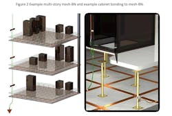
A mesh-BN is a supplementary bonding network (e.g. a data hall within a data center) to which all associated equipment cabinets and racks as well as cabling pathways (e.g. trays, conduits) are bonded together as well as at multiple bonding connection points, to the common bonding network (CBN).
The CBN includes a comprehensive set of interconnected metallic components that provide the means for an effective bonding and grounding infrastructure. This set of metallic components includes, but is not limited to structural steel, reinforcing rods, AC power conduits, cabling infrastructure (i.e. racks, cable trays, etc.) and associated bonding conductors.
The mesh-IBN is a supplementary isolated bonding network with components such as associated equipment cabinets and racks as well as cabling pathways that are electrically insulated from the CBN, except for one (1) controlled single point connection (SPC) location to the CBN.
Role of alternating current equipment ground (ACEG) busbars vs. ICT bonding busbars
When designing electrical and ICT bonding infrastructure, it is not uncommon for a design engineering firm such as kW MCE to be asked the following question: Do we need to have separate electrical grounding for electrical and ICT, meaning we have an electrical ground and an ICT ground?
While the bonding and grounding of a data center’s electrical service is outside the scope of the ANSI/TIA-607-E standard, coordination between electrical and ICT bonding and grounding systems is essential.
The information below describes a standards-based approach to the relationships of the ICT bonding infrastructure to the electrical power bonding infrastructure.
1. In a building environment—Where the primary electrical power services are provided, an electrical bonding busbar shall be provided, featuring a direct bonding connection to the exterior building ground ring and ground rods, as designed by an electrical engineer.
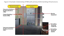
2. An ICT primary bonding busbar (PBB)—Shall be located near the primary ACEG busbar, with a telecommunications bonding conductor (TBC) attached by a licensed electrician, to bond these two busbars together.
3. The ICT secondary bonding busbar (SBB)—In a typical telecommunications space (e.g. telecommunications room [TR], an electrical service panel is often located within or very near to this ICT space, to serve the ICT equipment needs within the ICT space. In such cases, the alternating current equipment ground (ACEG) busbar shall be bonded directly to the SBB.
Overview of ICT bonding infrastructure
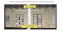
The ANSI/TIA-607-E ICT bonding infrastructure originates at the electrical entrance facility ground, which is external to the building, and then extends throughout the data center. The ICT bonding components include the following.
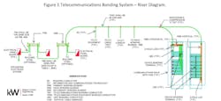
a) Primary bonding busbar (PBB): Serves as the ICT infrastructure’s pinnacle connection to the electrical service (power) building grounding electrode system. It is the central attachment point for the telecommunications bonding backbone (TBB).
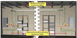
b) TBB: A bonding conductor that interconnects all secondary bonding busbars (SBBs) with the PBB. The TBB originates at the PBB, extends throughout the building using the telecommunications backbone pathways, and connects to the SBBs in telecommunications rooms (TRs).
c) Telecommunications bonding conductors (TBCs): Bonds the PBB to the electrical service (power) busbar, providing a direct path to ground (earth).
d) Secondary bonding busbars (SBBs, previously referred to as the telecommunications grounding busbar [TGB]): The bonding connection point for ICT systems and equipment in the areas served by each of the ICT spaces.
e) Secondary bonding conductor(s) (SBC): Used to bond the SBB to the TBB where the SBB is not bonded directly to the TBB.
f) Backbone bonding conductor(s) (BBC): Used to interconnect multiple TBBs through the associated SBBs, either on the same floor in a multi-story building or in the same general area of a single-story building.
Interconnection of electrical service ACEG busbar and ICT PBB
The PBB needs to be located near the building’s primary electrical service power panel (i.e., within the same space). The primary electrical service power panel contains the electrical service alternating current equipment ground (ACEG) busbar. A practical PBB location is to either side of the ACEG busbar.
The location and positioning of the PBB should provide for a short and straight pathway between the TBC and the ACEG busbar. The primary over-voltage, over-current protection bonding conductor must be installed near the PBB, to reduce the length of its bonding conductor. The TBC shall be, as a minimum, the same size as the largest TBB. For bonding conductor sizing of the TBC, TBB and BBC, reference ANSI/TIA-607-E, Table 1—TBB/BBC conductor size vs. length.
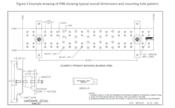
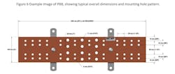
The PBB must be insulated from its supports, using an insulator that is listed for that purpose. A minimum of 50 mm (2 in) separation from the wall is recommended to allow access to the rear of the PBB.
The example drawing of PBB shows typical overall dimensions and mounting hole pattern.
When an electrical service ACEG busbar is not installed in the telecommunications entrance room or space, the PBB should be located near the backbone cabling and associated terminations, to provide access to it and to the TBB, extended back to the ACEG.
The PBB should serve telecommunications equipment that is located within the same room or ICT space. The PBB serves as the singular, central bonding busbar for the telecommunications bonding infrastructure. It also serves as the bonding busbar for equipment located in either the telecommunications entrance room or other ICT spaces.
Bonding conductors attached to the PBB and SBB
When an electrical service ACEG busbar is located within the same room or space as the PBB or SBB, that electrical service power panel’s ACEG busbar (when equipped), or the electrical service power panel enclosure, must be bonded to the PBB or SBB.
The telecommunications copper cabling, primary protector grounding conductor, must also be connected to the PBB or SBB. This conductor is intended to direct lightning and AC fault currents away from the telecommunications primary protectors. A minimum of 0.3 m (1 ft) separation is required between this conductor and any other DC power cables, switchboard cable, or high-frequency cables, even when they are placed in metallic conduit.
The connections of the TBC and the TBB to the PBB or SBB as well as the connection of conductors for bonding telecommunications equipment and telecommunications pathways to the PBB may use any of the following types of connections.
- Exothermic welding of two-hole lugs to busbar
- Listed compression two-hole lugs, fastened to busbar
- Listed exothermic two-hole lugs, fastened to busbar
Electrostatic dissipative flooring used in ICT spaces
To control the buildup and discharge of electrostatic energy in ICT spaces, a given ICT space may call for the provision of electrostatic dissipative flooring. Electrostatic discharges (ESD) may occur when a person is simply walking on a carpeted floor. Electrostatic dissipative flooring materials provide a safe and conductive pathway for potentially harmful static discharges, enabling such discharges to flow safely away from sensitive ICT network equipment, via an ICT bonding infrastructure.
When electrostatic dissipative flooring is used within a given ICT space, such as a TR, a bonding connection to the SBB will provide a low impedance bonding pathway. ICT professionals responsible for bonding such a flooring system shall follow manufacturers’ installation requirements. Such installation requirements may describe a soldering procedure of an insulated bonding conductor (wire gauge to be determined by manufacturer), to the exposed wall-mounted portion of the ESD grounding flooring foil(s), with connection(s) to the SBB.
In summary, each of the two (2) subsystems—the electrical power bonding infrastructure and the ICT bonding infrastructure—must have its own unique bonding busbars.
The PBB in each building shall be bonded, via the TBC, to the alternating current equipment ground (ACEG) busbar. The electrical path to ground (earth) is to be provided via the ACEG busbar, as described in this paper.
About the Author
Bob Faber, RCDD, NTS
Bob Faber, RCDD, NTS is ICT design studio manager with kW Mission Critical Engineering, a member of WSP. began his career as a structured cabling infrastructure professional in June 1982. His work experience includes structured cabling installation and design, along with ICT-systems integration. For more than three decades, he has developed and delivered structured cabling installation and design training curriculum. He is an active member and volunteer, having served as subject matter expert in the development of industry standards for organizations including BICSI, TIA, and NEMA.
