Installing voice circuits in residential and light-commercial buildings
Data networking is the glamorous end of the cabling business, but putting in standards-compliant telephone lines remains the bread-and-butter of many cabling contractors. These voice circuits also carry data and are crucial to many residential, home-office and light-commercial applications.
Technical Staff
Leviton Telcom
Installations in residential and light-commercial buildings are defined as having four or fewer low-voltage lines. The standard governing such installations is TIA-570, which is currently being revised. However, it is unlikely that the guidelines for proper installation of structured cabling will alter significantly.
The technology, terminology and procedures for this type of installation were developed by the telephone company, which, before the mid-1980s, was solely responsible for putting in such wiring. Following the divestiture of AT&T, however, independent contractors and customers were permitted to connect to the telephone company`s wiring.
These technicians were left with the basic two-wire, tip-and-ring circuit that supplies metallic continuity to the central office of the local telephone company. Over this basic circuit, the telephone company`s central office provides dial tone to premises. Each line from the premises that carries dial tone is connected to the central office with a dedicated pair of wires.
Telephone wire is required to carry both voice and data modulation. To handle both applications, telephone wire has three distinct characteristics: It is normally 22 or 24 American Wire Gauge in size; it is always connected in pairs; and the two wires in each pair must be twisted together to preserve signal quality.
Current telephone standards specify 24 AWG 4-pair unshielded twisted-pair (UTP) wiring for residential applications; 22 AWG may also be used and is desirable where low temperature or some other factor influences the rough-in wiring. Check the manufacturer`s specifications if in doubt.
Also, the cabling industry is considering requiring Category 3 UTP wiring as the minimum grade of cable for all residential applications. The purpose is to ensure minimum performance for home computer use and compatibility with future multimedia services.
Wire pairs are required because telephone systems provide all dialing and voice functions on dedicated circuits using direct current, calling for polarity to be maintained within each circuit. Consequently, each pair consists of a tip (+) and ring (-) wire.
Twisted-pair copper wiring is the most prevalent telecommunications medium. This wiring is relatively inexpensive, and when installed correctly, is capable of high performance. Each pair of wires is twisted together to prevent interference problems, such as induction and crosstalk. These problems arise from other pairs in the same cable bundle, as well as from outside sources such as power circuits and motors.
The rate and direction of twist is usually from 2 to 6 inches per twist counterclockwise, but it may be as tight as one twist in less than 0.5 inch. The tighter the twist, the less likely that the wire will be distorted during installation, and the greater the immunity to interference of the signals transmitted along it. In a given cable, each pair will be twisted at a different twist rate from other pairs in the same cable bundle to lessen interference between the pairs. This is an important point because it indicates that a telephone cable is a carefully engineered and precisely manufactured component, not just a random group of pairs bound together in a protective sheath.
While the specification for the rate of twist varies with the anticipated data rate to be carried by the installation, it is always proper installation practice to untwist the least amount of cable necessary to make a connection.
Quad wire--or 4-wire, untwisted telephone station wire--may be encountered where wiring systems are being expanded or upgraded, but it is no longer an acceptable medium for new multiline installations. Quad wire`s lack of pair twisting makes it susceptible to interference. Even in residential applications, the trend is toward increasing use of modems, fax machines, and ultimately, high-speed data devices.
In fact, many newer telephones and sophisticated telephone systems will not work properly unless connected to twisted-pair wire. Therefore, jacketed, four twisted-pair, color-coded telephone wire is recommended for all inside residential and light-commercial wiring.
Color-coding prevents confusion
Many twisted pairs can be contained in a single telephone cable, and these cables can be terminated at different points in a telephone wiring system. Therefore, strict adherence to a color code for each connection is essential to eliminate confusion during installation.
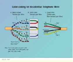
Two color-coding systems are used to maintain the separation of pairs and indicate polarity. Solid-color marking for inside wiring provides distinct, single-color identification of each wire. The standard color scheme for tip-and-ring wires, respectively, is:
- Pair #1: Green/red
- Pair #2: Black/yellow
- Pair #3: White/blue
The other standard telephone color-coding system identifies wire with a base color for the insulation jacket and a smaller band of a contrasting color repeated along its length. In each pair one wire is mostly the base color, with small swatches of the band color for the tip wire. The other wire is mostly the band color of the first wire, with small swatches of the base color; this is the ring wire for the pair.
Standard 4-pair, band-striped telephone wiring uses only five colors in distinctive combinations. The color combinations, coupled with the positioning of each color as either the base or the band, identifies the pair number, the tip wire and the ring wire in the pair, as follows:
Pair #1: White/blue
- The tip lead is mostly white (base) with blue bands. The ring lead is mostly blue, with white swatches.
Pair #2: White/orange
- Tip mostly white, ring mostly orange.
Pair #3: White/green
- Tip mostly white, ring mostly green.
Pair #4: White/brown
- Tip mostly white, ring mostly brown.
Proper installation is critical
The premises telecommunications wiring system should be installed using the proper wiring devices and techniques. Keep in mind, though, that these methods for roughing-in and installing telecommunications wiring and information outlets are basic procedures for residential and light-commercial applications only. Additional UTP installation requirements for commercial premises in compliance with the TIA-568A standard and its category requirements are also necessary.
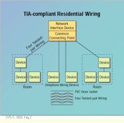
Two methods of installing telecommunications wiring are the star (often called "home-run" wiring) and the series (also known as "loop" or "daisy-chain" wiring) methods.
With star wiring, each telecommunications outlet is directly wired to the distribution device, which then becomes a common point for terminating all distribution wire runs and for originating all inside wire runs.
The star-wiring method offers many advantages. For example, if a wire is damaged during construction, the loss is confined to only that run instead of affecting all jacks beyond the damage. Because the damaged run can be isolated, the fault can be easily located with test equipment. And, if the customer wants to add additional telephone lines, the connections can be made easily at the distribution device, using spare pairs--there is no need to remove, rewire or replace jacks.
Series wiring involves running one continuous length of inside wire in the attic, ceiling or crawl space. Loops are then pulled from this run to the individual jack locations, forming a series of daisy-chained jacks. The series wiring method has serious drawbacks. Circuit breaks are difficult to locate. If a break or short occurs, power is lost to all jacks beyond that point in the series. Perhaps the most important disadvantage of this method, though, is that once wiring is installed in this way, it is almost impossible to make adds, moves and changes. The existing spare pairs are useless for additions because they can only be used for the single purpose for which they were originally installed. If telephones or other accessories need to be added, new wire must be pulled.
While the current TIA-570 standard allows both star and series wiring methods--including a combination where rooms are wired using the star method and outlets within a room are wired in series--the industry is moving away from series wiring, due to the disadvantages stated above. In fact, the TIA-570 revision in progress leans toward star wiring only, a recommendation that another industry organization, Wiring America`s Homes (formerly Wire America), will also be making. Wiring America`s Homes is currently considering a number of star-wired configurations, some of which include Category 5 UTP with various combinations of Category 5 jacks and F-connectors at each outlet.
This article was prepared by the technical staff of Leviton Telcom, Bothell, WA. It is adapted from the company`s recently published book, Installation Strategies for Long Term Cabling System Success.
Two color-coding schemes are used with telephone wiring--band-striped and solid-color. Band-striped color-coding (illustrated in A) depends on a dominant color and contrasting band color. Solid-color coding is illustrated in B. C shows color-coding for 4-wire, untwisted quad wire (also solid-color), but be advised that quad wire is no longer acceptable for new installations in multiline environments.
The wiring recommended for residences and light-commercial applications in the TIA-570 standard combines the "star" or "home-run" wiring method to be used from individual rooms to the common connecting point with series or "daisy-chained" wiring within rooms.
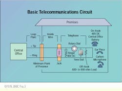
When telephone sets on the premises are not in use, their handsets are said to be on-hook. In this condition, there are normally 48 volts of direct current (DC) across tip and ring. This potential, known as CO battery, is heavily filtered DC supplied by a power source in the central office. When a telephone handset is picked up to place or answer a call, it is said to be off-hook, and a 600- to 900-ohm load is placed across the CO loop. This resistance load reduces the CO battery to 6 to 12V DC, which is known as talk battery (as opposed to CO battery). Normal off-hook loop current is 20 to 90 milliamps, depending on the distance to the CO, the resistance of the loop, and the number and electronic characteristics of the telephones connected to the loop.
When a number is dialed, calling signals are sent to the CO by one of two methods. A rotary-dial telephone, in series with the loop, makes and breaks the loop current through a contactor at a governed rate. These pulses are translated by the CO equipment to route the call. Tone dialing uses audio signals instead of pulses to transmit digits to the CO. The tone pad draws operating current from the talk battery to operate an internal tone generator and amplifier that place the correct audio tones on the CO tip and ring. These tones are called dual-tone, multifrequency signals.
The incoming ringing signal is delivered to the premises by pulses of 90V alternating-current (AC) power at a frequency of 20 to 30 hertz. A capacitor keeps the ringer from operating except when the AC ringing signal is present on the tip-and-ring pair from the CO.
Note that party lines and other specialized circuits operate in more complex ways and may need to be installed or maintained by the telephone company. In addition, some telephone companies are installing equipment at party-line locations to electronically convert special party-line circuits to standard straight-line wiring. This simplifies changes and additions to customer-owned portions of the wiring system. Before working in a building, be sure to check with the local telephone company for rules and requirements.
The demarcation point between the telephone company`s responsibility and that of the customer or building owner is the minimum point of presence. On the central-office side is the local loop, also known as outside-plant wiring. Within the premises is inside-plant wiring.


