Prepare for encircled flux before compliance issues arise
From the June, 2014 Issue of Cabling Installation & Maintenance Magazine
EF is becoming increasingly important as loss budgets tighten for high-speed transmission. Allowing for EF is one of four key components to successful Tier 1 testing.
by Adrian Young, Fluke Networks
Loss budgets for optical-fiber testing are becoming increasingly tight as more low-loss components such as LC/MPO cassettes are introduced. As a result, consultants and cabling vendors are beginning to specify loss budgets based on component performance, not standards. Any allowable slack in testing practices has disappeared, and to stay current installers need to re-evaluate their test equipment and procedures for Tier 1 optical-fiber testing.
Using an appropriate reference light source, setting the reference and using reference-grade connectors are all vital parts of the testing jigsaw puzzle. However, even when all of these are carried out correctly, two different testers can still achieve a variability of up to 40 percent. This, unfortunately, is the nature of optical-fiber testing. The fiber connection is considered random, hence the need to have a reference-grade connector. But additional uncertainty is introduced if the testers use two different light sources, even though the sources have been referenced out, due to the way the light is launched into the fiber.
Telecommunications Industry Association (TIA; www.tiaonline.org) standards initially defined the launch condition from a multimode optical source in terms of coupled power ratio (CPR). However, this still allowed too much variability between sources, so in 2010 the TIA and IEC created encircled flux (EF) to define launch conditions on multimode optical fiber (see ANSI/TIA-526-14-B or IEC61280-4-2).
EF refers to the ratio between the transmitted power at a given radius of an optical fiber core and the total injected power. It specifies the modal power across the entire endface of the test reference cord, which has to be maintained to the end of the cord.
At some point we can expect EF compliance to become mandatory in many optical-fiber test specifications developed by end-user customers, so installers need to begin considering now how to incorporate it into their field-test procedures. The initial standard does not specify this, although two options for meeting EF requirements are set out in TIA TSB-4979 Practical Considerations for Implementation of Encircled Flux Launch Condition in the Field.
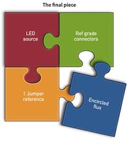
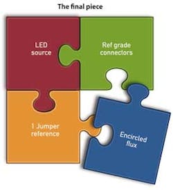
It is important to note that the initial definition of EF by the TIA and IEC assumed that installers were already implementing best practice for optical fiber field testing. Anyone working in technical support will know that this assumption often is untrue. To achieve optimum results when carrying out a Tier 1 optical loss measurement, all four aspects of testing must be set up correctly: 1) the LED source, 2) the jumper reference, 3) the connectors, and 4) the encircled flux requirement.
Let's look at each of these four aspects more closely.
Four aspects of testing
Choosing the right optical source. In theory, users can test multimode optical fiber links with either a vertical-cavity surface-emitting laser (VCSEL) or a light-emitting diode (LED). However, current ANSI/TIA regulations specify that the source must have a spectral width between 30nm and 60nm. This is easily achieved with an LED source. However, a VCSEL source has a spectral width of just 0.65nm, and its launch into the optical fiber varies substantially between different VCSEL sources, thereby increasing the measurement uncertainty to a point at which it is no longer acceptable. The VCSEL launch is also underfilled, resulting in an optimistic loss measurement reading.
If the optical-fiber system is tested with a VCSEL, the cabling vendor may not accept the application warranty due to the uncertainty of the measurement. It is the responsibility of the individual who is testing and providing the warranty for the system to ask what type of source is to be used. If in doubt, we recommend that the tester review the test equipment vendor's data sheet and verify requirements with the cabling vendor that is offering the warranty for their system.
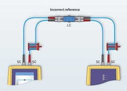
Setting the reference correctly. Setting the reference incorrectly can lead to optimistic and negative loss results. The latter are the largest cause of failed system acceptance and warranty denial, and suggest an amplification of the optical system, which is impossible in a passive system. It is essential to follow the industry standard and set a reference using a single test reference cord.
Common causes of error when setting the reference are the following.
• Setting a reference through a bulkhead adapter, which adds an uncertainty of up to 1.5 dB due to loss in the adapter. The reference has to be continuous from the source to the meter using one test reference cord (1 jumper).
• Not coiling the fiber around a mandrel, which could make results pessimistic by up to 0.4 dB as well as unstable depending on whether the source is overfilled or underfilled.
• Using bend-insensitive multimode fiber (BIMMF) test reference cords with dual-wavelength testers. The standard 25mm mandrel will not strip out the higher-order modes at 850 nm and will perform as if there was no mandrel. Likewise, using a 4mm mandrel would render 1300 nm measurements incorrect.
To achieve reliable results the tester should use equipment with interchangeable adapters on the input ports. This allows for setting a 1-jumper reference in accordance with TIA and cabling-vendor requirements. It is also important to purchase the correct adapters and cabling reference cords.
Using reference-grade connectors. Bad cords lead to poor and inconsistent test results. Standard ISO/IEC 14763-3 Testing of Optical Fibre Cabling defines reference-grade connectors as having a loss of <0.1 dB for multimode and <0.2 dB for singlemode. When the low-loss cassette has a 0.15-dB LC connector, testing it with anything worse than a 0.15-dB LC connector is going to yield a pessimistic result or potential failure.
If using a 1-jumper reference, the test reference cords can be verified. Once the 1-jumper reference has been made, the cords are removed from the input ports. A quality cord is then inserted into the input ports, the main and remote units are joined together using a singlemode rather than bulkhead adapter, and the test is run. The loss result should become part of the system documentation.
Allowing for encircled flux. TIA TSB-4979 describes two methods for meeting EF requirements. The first is to use an external launch conditioner, which replaces the mandrel. This can turn any LED source into an EF-compliant solution, avoiding the need to buy new test equipment. However, external launch conditioners are expensive, bulky and need to be replaced when the connector at the end breaks. Many data center managers operating to tight optical-loss budgets tell installers to include the cost of the launch conditioners in their bid.
The second option is to use an EF-compliant source with a tuned reference cord that strips out the unwanted modes. Although this is a proprietary solution and requires the purchase of new test equipment, the cords are less expensive and bulky than launch conditioners.
If existing test equipment has fixed input ports that do not allow a 1-jumper LC reference, installers could consider jumping two generations of testers and make testing of optical fiber both EF and 1-jumper compliant at the same time, in accordance with ANSI/TIA-526-14-B.
Best practice tips for installers
Tighter loss budgets and higher-data-rate systems are making EF increasingly important, and at some point user organizations and/or cabling-system manufacturers will make EF compliance mandatory for optical-fiber testing; it is already required for standard compliance.
We recommend that organizations review their field-test procedures and ensure their installers are following best practices. They should:
• Use LEDs as the light source, not VCSELS, to avoid optimistic results;
• Avoid setting references through bulkhead adapters;
• Use mandrels to remove higher modes, while remembering that they are not a substitute for EF adapters;
• Invest in optical-fiber test equipment with interchangeable adapters on their input ports;
• Verify test reference cords and not use BIMMF as a tester cord;
• Save measurements and make them part of test documentation;
• Create a strategy for EF compliance, bearing in mind that vendors may insist on a 1-jumper EF-compliant measurement before sending an engineer to troubleshoot a failing system.
Adrian Young is senior customer support engineer with Fluke Networks (www.flukenetworks.com).


