Provide adequate support for Category 5 horizontal cabling runs
Appropriate routing equipment for twisted-pair cable will ensure compliance with installation standards and smooth future moves.
Ray Keden, erico Inc.
Today, Category 5 cabling is the product of choice in wiring commercial and residential telecommunications installations. When properly installed, Category 5 cabling can keep a network running without the disruptions caused by data distortion, noise, and system degradation. Also, it is less expensive than fiber-optic cable on a cost-per-workstation basis. For these and other reasons, many cable runs from the telecommunications closet (TC) to the work area--referred to as horizontal cabling--consist of Category 5 cabling.
An important aspect of any horizontal cabling project is proper support for the cable. The support system provides a protective pathway and is designed to eliminate stress that can damage the cable. Typical cable-support systems include cable trays, ladder racks, enclosed wire pathways, clamps, rings, and fasteners. The support method you choose for your project will depend on the size, quantity, and placement of the pathways. When determining a cable-support method, you should consider three other characteristics: security of the hold, ease of installation, and cost-effectiveness.
Years ago, telephone cable was the standard horizontal wiring medium, and it could be counted on to work properly regardless of how it was configured in a building. However, Category 5 and other modern telecommunications cabling is sensitive to the bends and twists it is exposed to when being routed during installation. So, the cable-support system you choose should in addition hold the cable properly without placing stress on it or otherwise compromising its integrity.
Conduct preliminary research
Before you choose a support system, examine the area through which the cable will run to ensure that the paths selected can provide cable support. Also, determine the weight and type of cable you will install.
Regardless of what type cable is being installed, it is important to understand the Electronic Industries Association/ Telecommunications Industry Association (eia/tia--Arlington, VA) standards and the National Electrical Code (nec) sections that apply to telecommunications cabling. tia/eia-568a, the commercial building telecommunications cabling standard, describes the transmission media. eia/tia-569, which was updated in 1997, discusses pathways and spaces. eia/tia-607 covers grounding of telecommunications cabling, and eia/tia-606 applies to telecommuni-cations systems administration, including labeling and identification of cable runs. Residential telecommunications cabling is covered in eia/tia-570. Also, some chapters of the nec, including 770 and 800, apply to telecommunications wiring.
Other information, including installation manuals and up-to-date information on cabling practices and installation, is available through bicsi (Tampa, FL). Finally, you must know the local codes that will affect the way you install your system.
Getting as much information as possible is important because proper installation is crucial to the success of a telecommu- nications system. Improper installation, crimped cables, or a tight bend radius can all jeopardize the integrity of the network when data is sent through it at high speeds.
In today`s work environment, upgrades and retrofits of telecommunications systems are common. It is essential that installers consider future changes in work areas, and in the system itself, before making the initial installation. The installation should adapt easily to accommodate new workstations, office rearrangements, or complete system renovation. Many cable-support systems on the market today can accommodate changes while keeping down costs.
Generally, cabling can run from the TC to the work area over one of three routes: under the floor, above the ceiling, or in the walls. After leaving the TC, the cable is typically distributed in cable trays, over ladder racks, through raceways (conduit or duct), or using fasteners to utility poles, or modular furniture systems that link the cable to individual work areas. In environments in which office moves or relocations will be likely, consider using an open distribution system consisting of a combination of cable trays and J-hook fasteners. Conduit, while offering protection for delicate cable, can create problems when offices must be moved and cabling added to or removed from the run. Trying to pull new cable through conduit that is already partially filled can be difficult and time-consuming. An open system is easier to retrofit or upgrade, and in the long run, will be a cost-effective choice.
Cable trays and ladder racks are available in several styles and sizes, so installers should consult manufacturers` installation guidelines. Trays and ladder racks can be installed parallel to and against a wall, or suspended from the building structure using threaded rods. They can also be supported by fasteners.
Underfloor cable runs
Less than 2% of cable runs are made under a raised floor; most horizontal cabling is pulled through the ceiling. However, if you must run cable beneath a raised floor, here are some suggestions.
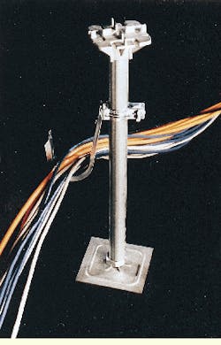
Keep the cables off the floor itself and organize them. As long as the space below the raised floor is at least 8 inches, the easiest way to run the cable is with pre-riveted J-hook assemblies attached to floor pedestals. J-hooks are ideal for most telecommunications wiring situations because they do not damage the cable. Bridle rings and cable ties, on the other hand, can crimp or otherwise damage the cable.
Other cable-routing options include raceways or wire ducts. They are completely enclosed pathways, which make changes or upgrades in the system difficult. While equally effective, particularly for large bundles, these methods can be significantly more costly and more difficult to install.
In-wall cable runs
In new construction, the easiest path in which to run telecommunications cabling is the wall. Cable is routed horizontally through holes in wood or metal studs. If the cables are closer than 11/4 inch from the front edge of wooden studs, the nec requires cables to be covered with a steel plate to protect them from being penetrated by screws or nails. The cable itself does not need fasteners in this situation; the studs become the cable supports. Because studs are generally located 12 to 18 inches apart, the distance between the studs is well within the recommended 4- to 5-foot span between fasteners necessary to adequately support the cable.
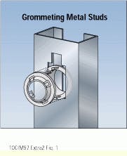
When working with metal studs, grommets placed inside the stud holes are needed to protect the cable from sharp metal edges. Metal stud punches and mating grommet systems are available that can be used to easily create a dedicated pathway for telecommunications wiring. Some grommets can be used with the existing holes that are stamped during the manufacture of metal studs.
Once the cable reaches the work area, use a low-voltage mounting bracket to attach a Class 2 communications outlet. Ideal for new construction, this outlet can be installed to the front or side of metal or wooden studs and will eliminate the bulge caused by plaster rings.
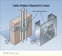
When cable is run parallel to the stud framing, it is best to follow code requirements for power cables. Position the cable 11/4 inch from the face of the stud. Whenever possible, the cable should be centered on the stud. This can be accomplished using prefabricated hangers that can support multiple runs of cable. These fasteners attach to the stud and grip the cable in place. Fasteners can be stapled, nailed, or screwed to wooden studs, or twisted into the existing hole in the metal stud.
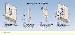
In retrofits, low-voltage mounting brackets are available that attach to the drywall and provide positive support using two locking screws. The brackets eliminate the need for an electrical box. They provide a better option than drywall anchors, which can loosen and sometimes crumble the drywall with normal use when plugging and unplugging.
Overhead cabling
Most data cabling running from the TC to the workstation is suspended from the ceiling. In some projects, heavy or modular tray systems are used to run large cable bundles that branch off from the TC. Heavy cable trays can be attached to the beam, purlin, or deck. Again, these systems are effective but more costly than other options.
Within suspended ceilings, the choice was once simple. Many installers pulled the cable directly across the ceiling. This approach is now prohibited by the nec, so a costly cable-tray system became the only option for most installations.
However, the tia/eia-569a standard, which incorporates revisions to the original pathways and spaces standard and was issued earlier this year, allows for mounting appropriate fasteners loaded with multiple cables to suspended-ceiling support rods or wires. The cable weight can be up to the approved weight-load rating for the fastener used. Also, the ceiling T-grid can be used to mount appropriate cable fasteners. When attached to the T-grid, the fasteners may carry a total weight of 0.45 pound per foot (0.7 kilogram per meter). The fastener design, however, cannot interfere with inserting or removing ceiling tiles. The cable must be positioned at least 3 inches above the ceiling tile.
Electrical cable cannot be hung in this manner because of safety problems that could arise in the event of a ceiling collapse. Telecommunications cable, however, can easily be suspended with prefabricated J-hooks that simplify installation and proper long-term cable support. The key to effective installation is to avoid placing any pressure or creating any stress points on the cable. Improper cable sag, narrow cable ties, and bridge rings can all create harmful stress points.
J-hooks can accommodate Category 5 cable, innerduct, and fiber-optic cable when mounted to structures above the suspended ceiling. Factory-riveted assemblies are available that can be quickly installed by anchoring them to structures such as beam flanges, "C" or "Z" purlin, deck, acoustical tee, drop wire, or the ceiling T-grid. Some J-hooks are manufactured with telecommunications cabling in mind. The curved edges and wide loop allow sensitive cable to lay smoothly, without crimping or cutting. J-hook systems are usually easy to install and are flexible in accommodating future system changes and upgrades.
A J-hook attached to an underfloor pedestal provides support for horizontal runs without stressing the cables.
Grommets protect cables from the sharp edges of holes punched in metal studs. The two sections of the grommet snap together to hold it in place.
A prefabricated hanger can be used to support multiple cable runs and align cables in the center of a wooden or metal stud.
Low-voltage mounting brackets eliminate the need for electrical boxes and will not loosen as drywall anchors are prone to do.
Ray Keden, registered communications distribution designer (rcdd), is manager for codes and standards with erico Inc. (Solon, OH). He is active in standards committees within tia, Underwriters Laboratories (Northbrook, IL), the Canadian Standards Association (Toronto, ON, Canada), and the National Electrical Manufacturers Association (Washington, DC).


