Crossover patch cords provide proper pin-outs
Robert Walls
Wiltel
Problem
When daisy-chaining Ethernet hubs (concentrators) with modular patch cords, you may sometimes find that your hubs cannot communicate with each other.
Solution
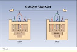
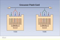
Connect the hubs with a "crossover" patch cord; that is, terminate one end of the patch cord using the T568A pin/pair assignment, and the other end with the T568B pin/pair assignment. This provides the correct installation of the transmit wire pairs (pins 1 and 2) and the receive wire pairs (pins 3 and 6). Having a quick and easy way to recognize the pinouts of a modular plug can make it easier to eliminate pin/pair assignment confusion and ensure that the hubs can communicate properly.
Procedure
1) Examine the modular patch cord plug and determine whether it follows the T568A or T568B pin/pair assignment. The T568A pin/pair is the sequence recommended by the Telecommunications Industry Association/Electronic Industries Association tia/eia-568a standard for terminating unshielded twisted-pair (UTP) cabling on 8-pin modular plugs and jacks. However, the T568B sequence, specified by the ieee 802.3 10Base-T Ethernet standard, is widely used.
2) The sequence of the pin/pair assignment is the order in which the incoming pairs are terminated into the modular pins. Each pair is designated as a tip (T) and ring (R) conductor; for example, pair 1 is designated as T1 and R1. To identify the pairs, 4-pair copper cable is color-coded. The primary color in color-code option 1 is always white and the secondary colors are blue, orange, green, and brown, in that order. Pair 1 is white/blue, for example, where one conductor is white with a blue stripe and the other conductor in this pair is blue with a white stripe. Similarly, pair 2 is white/orange, pair 3 white/green, and pair 4 white/brown.
3) Once you have identified the pin-out sequence for one end of the patch cord, go to the other end. Cut off the plug at that end and reterminate it using the other standard pin/pair sequence; that is, if the pin-out on one end of the modular patch cord is T568A, then you should reterminate the other end of the cord with the T568B pin/pair assignment. This ensures that pins 1 and 2 connect to pins 3 and 6.
4) When terminating the modular plug, always follow the tia/eia-568a standard guidelines; that is, allow no more than 1/2 inch untwist for Category 5 and no more than 1 inch for Category 4 UTP patch cords.
5) Test the patch cord when completed, and your tester will indicate a reversal on pairs 2 and 3.
Note: This type of crossover patch cord is typically used on lower-end hubs. Higher-end hubs generally have a built-in polarity-reversing capability.
In this crossover modular patch cord, the plug on the left has a T568A pin-out sequence and the other end has been reterminated to the T568B pin/pair assignment.
Robert Walls, installation manager at Wiltel (Marlborough, MA), submitted this article in the Installer Tips Contest at Cabling Installation Expo `96, held last October in Charlotte, NC.
This tip was compiled by Dennis Mazaris, registered communications distribution designer (rcdd), a design consultant at PerfectSite, 100 Glenn Drive, Suite A-11, Sterling, VA 20164, tel: (703) 450-8986, fax: (703) 450-9343, e-mail: [email protected].

