Matching block termination positions to work-area locations
Bill Spencer, Network & Communication Technology
Problem
In many situations when horizontal cabling is being installed, specific information identifying work areas is lacking. It can also be a problem to locate work areas?once they have been identified?after horizontal cabling has been terminated. When terminating to a patch panel or connecting block, the installer generally terminates and numbers horizontal cables sequentially, and this is not necessarily based on the location or identification of the specific work area served by a cable. For example, voice and data cables routed to a particular faceplate may be terminated at differing positions on the termination hardware in the telecommunications closet. Work-area identification is important, and in fact, required by the Telecommunications Industry Association/Electronic Industries Association standard 606 for telecommunications infrastructure administration.
Solution
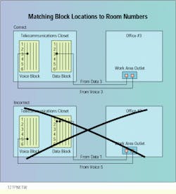
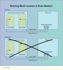
One way to solve this problem is to terminate all cables from a specific work area to the same position on each of the connecting-block or patch-panel subsystems in the telecommunications closet.
Procedure
1) Identify each subsystem in the horizontal cabling?for example, voice and data. Include all copper and fiber cable runs entering the telecommunications closet.
2) Terminate cables to a particular work area on the same position in each of the respective subsystems?for example, all cables from an office numbered 3 are terminated at the third position on each connecting block or patch panel. In this way, the work-area identifier becomes both the telecommunications-closet identifier and the position of the horizontal termination.
3) Contact the customer or architect to make sure that these identifiers are added to existing blueprints or cabling diagrams.
4) Label each position on the voice and data connecting blocks or patch panels with the appropriate sequential horizontal position number.
5) Label the faceplates in each work area with the correct work-area identifier.
6) Label or color-code voice and data jacks at each work area to indicate the subsystem to which each belongs.
7) When room numbers are eventually assigned, create a table indicating which work areas are located in each room.
Note: If there is not a consistent structure to the cabling routed to all work areas?for example, one voice and one data line to each?then there can be empty positions on the connecting blocks and patch panels in the telecommunications closet.
Using horizontal cable termination positions from the telecommunications closet to build work-area identifiers and identify connecting blocks.
Bill Spencer is president of Network & Communication Technology, Park Ridge, NJ. His company specializes in telecommunications administration software systems.

