The transmission signal in video coaxial cable relies on the cable's structure and electrical properties.
How does a signal travel through a video coaxial cable? Georg Simon Ohm is the author of "Ohm's law," a theory that the communication of electricity occurs between "contiguous particles." As we examine coaxial cables, we must take notice of Ohm's law as the father of this medium.
Ohm's law defines cable impedance. The key tenet of all transmission line theory is that the source impedance must be equal to the load impedance to achieve maximum power transfer and minimum signal reflection at the destination. In coaxial cables, signals are transported instead of radiated. Video coaxial cable needs a strong signal to achieve the highest performance. If a signal is radiated, the signal loses energy when it comes into contact with other elements before it ends up at its destination.
We will look inside the video cable itself to examine just how it transports signals. This article will expose the elements of the coaxial cable and discuss electrical properties that compose the coaxial cable in video applications. Also, the article will examine how coaxial cable battles against signal loss.
A breakdown of the components
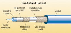
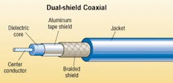
A coaxial cable consists of a center conductor, a dielectric core, a shield, and a jacket. Let's start with the center of the coaxial cable and venture outward.
Center conductors in coaxial cable are either solid or stranded wire. In video applications, a solid center conductor is recommended for termination purposes. "If you're putting a BNC connector, the connector used for video, on the coax, it is recommended to use a solid conductor because the conductor is exposed in the BNC connector," says Richard Stearns, national sales manager, Quabbin Wire & Cable Co. "A stranded conductor would not let the male end of the BNC connector insert into the female end of the connector." Typically, a stranded wire conductor is designed for cable flexibility. "With such a large center conductor already giving the coaxial cable so much bulk, it typically isn't flexible anyways," adds Stearns. A larger center conductor is needed for longer cable runs. For longer distances, Stearns suggests a 20-gauge conductor, as opposed to a 26-gauge conductor for shorter runs.
Copper is the most common metal used for center conductors in video applications. Bare copper is recommended for optimum performance in video signal transmission. Since a video signal has low-frequency components, the low DC resistance that copper provides will improve the video signal transmission.
A dielectric core provides an insulation for the center conductor as well as maintains physical support and a constant spacing between the inner conductor and the outer shield. When the insulation affects the signal being carried on the wire, it is called a "dielectric." Plastics, as well as other materials, can be compared with a number that describes dielectric quality, called a "dielectric constant." Vacuum is the standard by which all other materials are compared, and therefore, has a dielectric constant of one. Since air has a dielectric constant so close to one, air is viewed as the ideal dielectric, in terms of efficiency. Stearns explains, "if you introduce air into a solid compound, you are actually creating foam cells, which is trapping air in the dielectric." However, air does not offer any structural support, so cable companies use hydrocarbon-based materials such as propylenes. Foamed fluorinated ethylene propylene (FEP), otherwise known as Teflon, is close behind air with a dielectric constant of 2.1. "A lower dielectric constant translates to a better transmission at higher frequencies," says Stearns. The dielectric material and its composition are critical as it sets up the electrical properties.
Certain organic plastics such as polypropylene and polyethylene exhibit less absorption than others and are consequently better suited for carrying AC signals. When AC signals propagate through wire, some of the energy is lost as heat (think of Ohm's law). This effect may be overcome by using a larger-diameter wire. As AC signals increase in frequency, they have a tendency to be absorbed by, rather than pass through, insulating materials.
The coaxial shield, also called the outer conductor, is normally composed of a foil/braid combination. Foil shield is aluminum bonded to both sides of a polypropylene or polyester tape to provide 100% coverage; braid is flexible wire woven around the dielectric. For video applications, the Electronic Industries Alliance (EIA-www.eia.org) states a requirement for dual-shielded cable with 100% foil coverage and a minimum 59% braid coverage. "In almost all video applications, there is an aluminum (foil) shield first," explains Stearns. "If you put only a braid shield on, you will never get 100% coverage. The aluminum is put on with a 'cigarette-wrap' process, which involves the aluminum overlapping where the seams are to give the cable 360-degree protection." Several combinations of foils and braids are used to achieve various levels of shielding performance. "If the jacket sheath is cut for some reason, the braid will provide some degree of protection for the dielectric," says Stearns. More layers provide more protection and better protects the signal.
Even with the proper match of cable and connector, there is always some signal radiating through the coverage. Hence, the outer conductor also functions as a shield to reduce coupling of the signal into adjacent wiring. More shield coverage means less radiation of energy and protection from electromagnetic interference (EMI).
Jacket choice can vary according to the application. The jacket provides two major functions. One duty of the jacket is to provide protection from the elements a cable may be subjected to, and the second is to provide solid termination. Polyvinyl chloride (PVC) is recommended for most applications inside buildings. PVC is used for video applications since "it is flexible, relatively inexpensive, and usually has flame retardants added to it," says Michael Piner, process engineering manager, Harbour Industries. "Cost is always a driver."
Electrical properties
In coaxial cables, four electrical properties, all related to the dielectric constant of the core material and cable dimensions, determine the quality of the signal. Electrical properties such as impedance, capacitance, attenuation, time delay, and velocity of propagation are derived from the materials you choose.
Impedance defines the relationship of voltage and current in a coaxial cable. The most typical cable impedances used are 50- and 75-ohm coaxial cables. For video applications, a 75-ohm cable is used. How does the manufacturer determine what makes a 75-ohm cable? The characteristic impedance of a cable is determined by the formula 138 log b/a, where b represents the inside diameter of the outer conductor, and a represents the outside diameter of the inner conductor. This is a constant.
Capacitance, like impedance, is dependent upon the dimensions of the inner and outer conductors and the dielectric constant of the core. A capacitor is a device that holds an electrical charge. It consists of two metal plates with insulation in between. Sounds like the description of a coaxial cable? Capacitance is affected by the frequency of the signal on the cable. The higher the frequency, the more the capacitance "stores" that signal as a charge. This effect changes with frequency. In other words, the lower your capacitance, the longer the coaxial cable you can use.
Attenuation is common in all cables. This is the decrease in signal strength as it is transmitted through the cable. It results from electrical losses in the conductor and insulation. Low attenuation means that signals can travel farther without being boosted. Coaxial cables offer low attenuation since its dielectric materials help signals travel so well.
Time delay is also dependent upon the dielectrics of the cable. It is proportional to the dielectric constant. It describes the time that it takes for the signal to travel through a cable. The lower the dielectric constant, the less time is required for a signal to travel through the cable. This helps to prove that a dielectric with a higher percentage of air will carry a stronger signal.
Velocity of propagation compares the speed of a signal down a wire to the speed of light. The speed of light in a vacuum (100% velocity of propagation, by definition) is the standard by which all other signals are measured. The reason there is such an effect is because the signal consists of an electromagnetic field around the wire. That field travels in the plastic or other insulation of the wire. Materials such as FEP or polyethylene will give you lower capacitance and a higher velocity of propagation. Velocity of propagation is expressed as a percentage. Piner says that "polyethylene has a signal traveling through it at about 66% of the speed of light, and by injecting air into the dielectric, it can be improved to as much as 88%." However, too much air would cause the cable to collapse from lack of support. The dielectric material is needed to separate the inner conductor from the outer conductor.
Testing for performance
When evaluating the coaxial cable, a common argument is cost versus performance. Is the performance of my coaxial cable worth what I am paying for it? "A driving force is attenuation," says Piner. "People who are purchasing cables are always doing a 'cost per dB' analysis. How many dollars is it going to cost to get the performance I need?"
Steve Sterling, product manager, Coleman Cable, describes two tests done to examine the performance of a coaxial cable. In a "vertical tray test," "basically, you set up a cable tray about ten-feet-long, and at the bottom, you set up a Bunsen burner that puts a flame horizontally at the bottom. The test lasts ten minutes and the flame is not supposed to spread to more than six feet." This tests the durability of the cable. Sterling also describes a test that evaluates the frequency along the entire cable called a "sweep test." Using a standard tester, you can make a "sweep" to gather measurements at different frequencies. This will help you obtain a more accurate reading of the attenuation.
You need to test to your coaxial cable just as with other data cables to make sure you get what you pay for. Look inward. All coaxial cables may look the same, but if you look below the surface, you will find just what sets video coaxial apart from the rest.
Ryan Clicheis Assistant Editor of Cabling Installation & Maintenance.
null


