Cabling considerations for 10-Gigabit Ethernet
The technical details of the forthcoming IEEE standard will impact many network managers.
Christopher T. DiMinico/Cable Design Technologies Corp.
The exploding demand for Internet access to Web-based applications, as well as integrated multimedia voice/data/video applications, has fueled the need for higher-bandwidth networks. Rapid advances in microelectronics and optical networking technologies are enabling such increased bandwidth capacity.
Meanwhile, the Gigabit Ethernet network standards, promulgated by the Institute of Electrical and Electronics Engineers (IEEE-New York City), are evolving at the speed of light. Officially ratified in June 1998, the 1-Gigabit Ethernet standard was developed in approximately 2 1/2 years. And the current project of the IEEE's 802.3ae Task Force-the development of an industry standard for 10-Gigabit Ethernet-received preliminary approval in March 2000 and remains on track for ratification in early 2002.
In contrast to this rapid change, telecommunications cabling infrastructure changes at a significantly slower rate. In fact, a primary intention of cabling standards, such as the TIA/EIA-568 standard series and the ISO/IEC 11801 specifications, is to provide the end user with a useful life in excess of 10 years.
These two apparently conflicting trends create a dilemma for designers of fiber-optic cabling systems: how to keep pace with the rapid development and deployment of the Gigabit Ethernet standards in order to adequately specify a cabling system that can support Gigabit Ethernet applications.
Cabling distance concerns
Structured cabling system end users expect application independence. They want to be able to change and move networking equipment without having to add new cabling. In other words, they want plug-and-play connectivity. Recognizing this need and expectation, the IEEE targeted the distance specifications in TIA/EIA-568A and ISO/IEC 11801to allow end users plug-and-play capability with Gigabit Ethernet devices.
But technical issues relating to the use of laser sources with multimode fiber systems required a scaling of the distances for 1000Base-SX-the 850-nanometer short-wavelength laser-based form of Gigabit Ethernet-from 300 meters to 220 meters. The same technical issues also required the use of a mode-conditioning patch cord for 1000Base-LX-the 1,300-nm long-wavelength laser-based form of Gigabit Ethernet. In short, Gigabit Ethernet users could not simply plug-and-play with TIA/EIA-568A-compliant cabling.
For a fiber-optic cabling system to comply with the TIA/EIA-568A cabling standard, it must employ 62.5/125-micron multimode fiber with a modal bandwidth of 160 MHz-km at a wavelength of 850 nm, and a modal bandwidth of 500 MHz-km at a wavelength of 1,300 nm. (MHz-km is a bandwidth-length product that characterizes how far a transmission system can operate at a specified bit error rate.) Multimode fiber's information-carrying capacity is typically measured in MHz-km. The TIA's specification of 62.5/125-micron fiber in the standard was based on the fiber specified in Fiber Distributed Data Interface (FDDI) systems, enabling fiber backbone distances to 2 km. Also, and importantly, the 62.5/125-micron modal bandwidth is specified with an overfilled launch (OFL) characteristic of light-emitting diodes (LEDs).
The 568A standard also specifies 62.5/125-micron fiber interbuilding and intrabuilding backbone distances to 2,000 meters and 500 meters, respectively. The TIA/EIA Telecom-munications Systems Bulletin TSB-72 Centralized Optical Fiber Cabling Guidelines allows for a combined length of the horizontal, intrabuilding backbone, and patch cords to 300 meters (984 feet).
Bandwidth variables
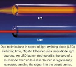
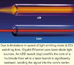
During the development of the 1-Gigabit Ethernet standard, researchers discovered that the multimode fiber bandwidth achieved during laser-based transmission was lower than the bandwidth achieved with LED-based OFL transmission. And due to limitations in the speed of LEDs' switching time, Gigabit Ethernet uses laser-diode light sources rather than LEDs that have been limited to 622 Mbit/sec Asynchronous Transfer Mode applications.
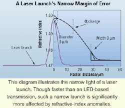
As the OFL characterization indicates, an LED launch fills the fiber core with light. A laser launch, on the other hand, is much narrower. And defects that can occur in the fiber-manufacturing process, coupled with the laser's narrow launch, can have a substantial effect on transmission capability. Specifically, manufacturing-process defects can alter the ideally smooth parabolic shape of a fiber's refractive index.
A fiber without a smooth parabolic refractive index is subject to differential mode delay (DMD), which is the difference in propagation time of different mode groups within the multimode fiber. DMD is, in some ways, like delay skew in copper cables. This DMD results in degraded fiber bandwidth. A narrow laser launch is more affected by refractive-index peaks and dips than a broader LED launch. And, remember, only lasers are used for Gigabit Ethernet transmission.
In response to the need for higher-bandwidth fiber-optic cabling specifications, the TIA's TR-42 Engineering Committee has generated the Optical Fiber Cabling Standard TIA/EIA-568B.3. One of the important ways that this standard differs technically from the 568A standard is that it includes 50/125-micron fiber-optic cables. Also of significance, the performance specifications for 62.5/125-micron optical fiber remains unchanged.
Additionally, to keep pace with the development of 10-Gigabit Ethernet, the TR-42 Committee has developed an addendum to 568B.3 that is currently in industry ballot. It provides additional transmission-performance specifications for 50/125-micron optical fiber capable of supporting 10-Gbits/sec serial transmission up to 300 meters using 850-nm nominal-wavelength lasers.
Optical-fiber cable measurement specifications are also under development in the TIA FO-2.2.1 Task Group. These cable-measurement specifications impact both the 10-Gigabit Ethernet standard and the 568B.3 addendum. The fiber-optic cable transmission-capacity measurements referenced in TIA's 568A and 568B.3 standards are insufficient to characterize the laser-launch bandwidth. The Task Group expects to complete its work before the release of the 10-Gigabit Ethernet Working Group ballot in March.
In March 2000, the IEEE Computer Society 802.3 LAN MAN Standards Committee approved a project to develop a supplement to the Ethernet standard to support operation at a data rate of 10 Gbits/sec. The 10-Gigabit Ethernet standard defines two unique physical layer specifications: the LAN physical layer (LAN PHY) and the WAN physical layer (WAN PHY). The physical layer (PHY) portion of the standard contains the types of transmitters, receivers, and encoding functions that translate the data into signals compatible with the cabling type that will be used.
The primary difference between the LAN PHY and the WAN PHY is the targeted operating environment and the type of data coding used. The WAN PHY operates at a rate that is compatible with the Synchronous Optical Network (SONET) OC-192c/SDH VC-4-64c and the dense wavelength division multiplexing (DWDM) optical network. Both PHY types will support the same cabling types and operating distances.
Each successive Ethernet standard has provided a factor-of-10 data-rate improvement, advancing from 10 to 100 to 1,000 and now to 10,000 Mbits/sec over the past decade. For that reason, compatibility with existing Ethernet topologies, including cabling types and distances, has always been a goal of Ethernet standard development. Such compatibility allows product offerings that bridge between lower-speed and higher-speed Ethernet networks.
Ethernet in LAN and WAN
Ethernet traditionally has been associated with the LAN and extended LAN topologies. The Ethernet extended LAN is a topology associated with a corporate enterprise that requires networking to multiple remote locations. The distinction between the corporate Ethernet extended LAN PHY and the 10-Gbit/sec Ethernet WAN PHY is that the latter is targeted at commercial carriers' and providers' service-based networks, as well as corporate enterprise networks.
The WAN PHY specification enables 10-Gigabit Ethernet end-to-end connectivity over the current WAN infrastructure operating at OC-192c/SDH VC-4-64c, and over DWDM photonics networks. Unlike the SONET interface, which requires highly accurate synchronous clocks, the Ethernet WAN PHY is an asynchronous interface that requires far less complexity in the clocking functions. This relative simplicity in clocking functions reduces the cost of these Ethernet devices.
Developers of the standard anticipate that the Ethernet WAN PHY will provide levels of functionality equivalent to the current WAN implementations, while reducing the cost and complexity. The benefits of Ethernet in the LAN will be extended to Ethernet in the WAN. And Ethernet across the LAN and WAN infrastructure will offer commonality in equipment, eliminating the need to translate between protocols.
Physical layer specifications
Cabling performance and cabling topology are key considerations in both network design and implementation. As noted earlier, networking standards such as Ethernet include a physical-layer specification. That physical layer specifies the cabling requirements, including the cabling-transmission performance and the size of the network topology (i.e., cabling distances).
The 10-Gigabit Ethernet physical layer specifications are targeted at the LAN and extended LAN, the WAN/RAN/MAN, and storage area networks (SANs)-a class of networks associated with attaching storage devices.
The physical layer specification includes both serial and WDM fiber-optic transceiver options. In a serial-transmission implementation, signals are transmitted over one wavelength on each fiber.
The portion of the physical layer responsible for interfacing to the transmission medium is called the physical medium dependent (PMD) layer. Operating distances for 10-Gigabit Ethernet are specified for both multimode and singlemode fiber. The minimum operating distances for each option are associated with the targeted operating environments, such as the LAN, MAN, or SAN.
Similar to previous-generation Ethernet protocols, the nomenclature of the different 10-Gigabit Ethernet iterations include designations. For example, for the serial transceivers, in 10GBase-SR/SW, the "S" stands for short-wavelength, the "R" for LAN PHY, and the "W" for WAN PHY. Similarly, 10GBase-LR/LW is a long-wavelength specification, and 10GBase-ER/EW is an extra-long-wavelength specification. 10GBase-S uses an 850-nm transceiver and two multimode fibers; 10GBase-L uses a 1,310-nm serial transceiver and two singlemode fibers; 10GBase-E uses a 1,550-nm serial transceiver and two singlemode fibers.
The LAN PHYs, designated with the R, use 64B/66B encoded data; the WAN PHYs implement an encapsulation of the 64B/66B encoded data for compatibility with OC-192c/SDH VC-4-64c. So, the suffix designation SR refers to a short-wavelength PMD for the LAN PHY, and the suffix designation SW refers to a short-wavelength PMD for the WAN PHY.
The type and cost of laser specified for each PMD is related to the optical power necessary to achieve the operating distances. The primary per-port cost of the network device is driven by the cost of the optics used.
A large percentage of the 10-Gigabit Ethernet market will implement short-distance applications. The 10GBase-S 300-meter multimode application space has been identified to include TIA/EIA-568 and ISO/IEC structured cabling applications, including backbone and equipment-cable distances, as well as Internet data-center, central-office, and computer-room applications.
As stated earlier, the speed with which the IEEE has produced Ethernet specifications has historically posed significant challenges to cabling-system planners, who typically rely on TIA/EIA or ISO/IEC standards to design long-lasting network infrastructure systems. Perhaps the task is more demanding now than it ever has been, with a 10-Gigabit Ethernet standard on a fast track for ratification.
But a solid understanding of some of the technical details that concern the IEEE-details that frequently steer the direction of Ethernet standards-should allow cabling-system planners to comprehend their clients' current needs and anticipate their future needs.
Christopher T. DiMinico is director of technology for Cable Design Technologies (CDT) Corp. He works out of the Mohawk/CDT offices in Leominster, MA. He is a member of the TIA's TR-42 Engineering Committee and the IEEE's 802.3ae Task Force, and serves as a liaison between the TIA and IEEE.


