What equipment will be necessary when LANs adopt 10-Gbit and faster speeds?
With the advent of higher data rate, dense wavelength-division multiplexing (DWDM) all optical networks (AONs), the testing requirements and equipment are evolving rapidly.
Historically, testing requirements for optical communication networks have been limited to traditional measurements, such as attenuation, event reflectance, and total optical return loss. But these measurements could only provide limited information on the condition of the fiber. Still, they were suitable for the transmission systems being deployed at the time.
But today's testing now must include measurements such as chromatic dispersion, polarization mode dispersion, and optical channel analysis.
Technicians need to stay abreast of these latest testing developments to maintain optimal testing ability and efficiency. And even though these considerations affect the day-to-day business of public-network technicians, it is only a matter of time before they make their way into customer-owned campus environments.
Getting a handle on soaring rates
Time-division multiplexed (TDM) data rates of 10 Gbits/sec are prevalent today, and the networking industry is on the verge of widescale deployment of 40-Gbit/sec TDM systems. In addition, network span length is increasing, with some public systems achieving well over 2,500 kilometers without electrical regeneration. These two factors-increasing data rate and increasing span length-result in the need to measure and compensate for dispersion.
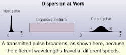
A transmitted pulse broadens, as shown here, because the different wavelengths travel at different speeds.
Dispersion is the name given to pulse broadening or spreading due to properties of the fiber and transmitted light. Basically, if pulses of data are sent very close together, as is the case with high-data-rate transmissions, and they disperse, they will blend into each other. The receiver will not be able to discern where one pulse ends and the next begins.
This data jumbling is termed inter-symbol interference, and causes a degradation of the network's performance. In singlemode systems, the two main types are chromatic dispersion (CD) and polarization mode dispersion (PMD). To fully appreciate and comprehend the nature and effects of these phenomena, it is important to understand their causes.
Nature of chromatic dispersion
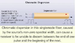
CD results from different wavelengths of light traveling in an optical fiber at different speeds. Even though today's transmitters have very narrow spectral widths, digital transmission signals inevitably contain a small range of wavelengths. That means different components (wavelengths) of the signal travel at different speeds, resulting in a broadening of the transmitted pulse.
Chromatic dispersion in this singlemode fiber, caused by the source's non-zero spectral width, can cause a receiver to be unable to discern between the end of one pulse and the beginning of the next.
Fortunately, test equipment that can measure the chromatic dispersion present in a system is readily available. Measured parameters typically include the zero-dispersion wavelength and the chromatic dispersion slope. Once these properties are known, the negative effects of CD can be removed or compensated for by adding dispersion compensation modules (DCMs).
The procedure of measuring the CD in a span and controlling it with a DCM is called dispersion-compensation engineering. Measuring and compensating for the exact amount of CD present in a link allows for the most accurate and efficient dispersion-compensation engineering, and helps optimize network performance. Nearly all DWDM systems, where multiple wavelengths are transmitted simultaneously at high optical powers and high bit-rates, require accurate measurement of CD and some form of dispersion compensation.
The problems of PMD
Once CD has been adequately compensated, PMD becomes the fundamental limiting factor in high-data-rate systems. Once largely unknown or ignored, PMD is increasingly on the minds of system planners and fiber-optic test engineers. Accordingly, PMD testing has emerged as an important new technology.
Testing is necessary to verify the ability of a particular fiber span, especially an old fiber, to carry high-data-rate signals. Experience has shown that most new fiber is capable of carrying 10-Gbit/sec signals, whereas many older fibers contain too much PMD to carry these signals.
As a general rule, whenever a data rate exceeds 2.5 Gbits/sec, a PMD test should be performed. Even newly installed fiber may be subject to large PMD values due to changing environmental conditions or rough handling.
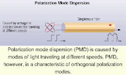
Polarization mode dispersion (PMD) is caused by modes of light traveling at different speeds. PMD, however, is a characteristic of orthogonal polarization modes.
PMD is a form of dispersion caused by the fiber propagating various polarization states of light at different speeds. A singlemode fiber can actually be viewed as having two propagation paths-one slow, the other fast. Certain polarization states of laser light are apt to travel in the slow path, while other polarization states are apt to travel in the fast path.
If these paths propagated light at the same speed, there would not be a problem since all of the light would arrive at the receiver at the same time. But this is not the case. Instead, these two paths propagate at slightly different speeds, so the light they carry arrives at the receiver at slightly different times.
One of PMD's most problematic properties is that it is influenced by external factors. This means that cables subjected to vibrations, temperature fluctuations, or any movement like wind buffeting an aerial cable, will have unstable and dynamic PMD values. It becomes important to "profile" a fiber by taking many PMD measurements over time to monitor the fiber's fluctuating PMD level. Some PMD test equipment currently available may be deployed and left unattended to provide this necessary long-term monitoring.
The very nature of PMD also results in the fact that the PMD for a given piece of fiber will be different if that fiber is on a spool or buried underground in a bundle. So, PMD measurements should be taken on fiber reels to verify the quality of the fiber, and made again after the fiber is installed. Periodic PMD measurements may also need to be performed, especially in areas where the ground is likely to shift or the cable is hung aerially, causing changing levels of stress on individual fibers.
In addition, due to its variable nature, PMD can have different affects on the different fibers within a multifiber cable. So unfortunately, knowing the PMD properties of one fiber in a multifiber cable provides very little information on the other fibers in that same cable. Each fiber must be tested independently. When performing PMD tests in today's large-count cables, the speed of your PMD-testing equipment, therefore, becomes paramount.
In general, the total dispersion present in a link-both CD and PMD-must be limited to 10% of the bit rate. For example, for 10-Gbit/sec transmission, the bit rate is 100 picoseconds (ps). So, the total dispersion should be less than 10 ps. It is important to remember that the negative effects of all dispersion accumulate with distance, so the longer the transmission link, the more susceptible it will be to dispersion's debilitating effects.
AONs, optical channel analysis
Dispersion has become increasingly important, as escalating bit rates have decreased bit times. But leading-edge networks not only increase bandwidth by transmitting faster; they also transmit on multiple wavelengths and keep the transmitted signal in the optical domain through the entire network. Each wavelength that is transmitted is called a channel and acts as a virtual fiber. In today's DWDM systems, one fiber may carry as many as 400 channels.
In addition to DWDM technology, many new optical components are available and deployed in efforts to increase bandwidth and lower cost. Erbium-doped fiber amplifiers (EDFAs) let network engineers increase the distance between regeneration sites, thereby helping to reduce operational costs. Optical switches are also deployed to replace larger, more-expensive electrical switches. Moreover, electrical switches also require the optical signal first to be converted to an electrical signal, which must then be switched and retransmitted. This is not only inefficient, but also introduces an additional receiver and transmitter into the system-increasing cost and introducing additional points of potential failure.
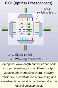
The optical wavelength converter is another component that has recently been developed to increase network efficiency. This device can shift an input wavelength to a different output wavelength. Such wavelength conversion allows for increased wavelength utilization, and thereby increases overall network efficiency. A combination of both switching and wavelength conversion can be found in the optical crossconnect.
An optical wavelength converter can shift an input wavelength to a different output wavelength, increasing overall network efficiency. A combination of switching and wavelength conversion can be found in the optical crossconnect.
These new components, although allowing for increased efficiency and bandwidth, result in a plethora of testing challenges. To increase efficiency, a signal in an AON may change wavelengths as it enters different portions of a network. Or, it may be routed to a different link to bypass a fiber break. As a result, today's technicians must know how many channels should be present, when they are supposed to be present, and what wavelengths each fiber should contain. With optical switches, optical-wavelength converters and optical crossconnects built into a network, technicians are looking for very dynamic signals.
Testing these AONs requires a tool specially developed for the task-the optical channel analyzer (OCA). An OCA is similar in operation to the optical spectrum analyzer, but is designed specifically to measure the required parameters in the telecommunications-transmission bands.
Each channel is represented by a spike, with the height of each spike indicating the optical power contained within that channel. Often, the information will be presented in graph and table view, which makes it possible to obtain highly detailed information about any channel present in the system.
The OCA provides information on which channels (wavelengths) are present, spacing between these channels, power in each channel, and how much each channel's wavelength changes with time (a phenomenon known as drift). When these testing mechanisms are deployed strategically throughout a network, users can gain information on components within the network. It is possible to monitor an EDFA's gain characteristics, the performance of a wavelength-division multiplexer, the operation of an optical switch, and other devices.
In response to the demand for increased bandwidth and lower operating costs, fiber-optic transmission systems are constantly evolving, creating new testing situations and scenarios. The emergence of CD and PMD test requirements, along with the increased need for optical channel analysis, are merely the next step in network-test evolution.
To remain competitive, it is more important than ever for fiber-optic technicians to stay abreast of the latest testing techniques and equipment. By combining and employing all of these new technologies, engineers and technicians will increase their testing efficiency while helping to optimize network performance.
Aaron T. Deragon is dispersion-measurement-systems product manager with GN Nettest's Optical Division (Utica, NY).


