Whats in a decibel, and why should you care?
At last, the science behind the industry`s most prominent performance symbol is explained.
Valerie Rybinski
The Siemon Co.
The decibel (dB) is considered the baseline by which all telecommunications designers compare cabling-system performance. But what exactly is a dB? Furthermore, what`s so significant about one system performing a few dBs better than another system?
The answer to these two questions traces back to the terminology`s origin. The decibel was first used to measure the intensity of sound. It`s a convenient way for engineers to describe the input or output of either power or voltages. And specifying performance in units of decibels has several benefits.
A decibel is generic; it can be used to describe performance independently of an application`s operating voltage or power.
The logarithmic scale on which a decibel is calculated allows performance specification across a broad range of voltage and power.
Decibels facilitate calculations and graphical solutions because you can add and subtract them, rather than multiplying or dividing their corresponding ratios.
From a practical standpoint, transmission performance is most commonly specified in units of dB.
For the simplest view of the decibel function`s operation, assume a reference voltage of 1. When you plug the 1-volt figure into the decibel function and solve for the corresponding decibel that relates to half of the signal strength (0.5V), the solution shows that a 6-dB performance improvement results in a 50% reduction in signal strength.
What does this formula (6 dB = a 50% signal-strength reduction) mean with regard to cabling systems? A few things. For example, it means a 6-dB crosstalk requirement would translate to 50% of the signal voltage being allowed to couple onto adjacent pairs. A 6-dB return-loss requirement would allow 50% of the signal voltage to be reflected back on a transmission line. And a 6-dB attenuation requirement would permit 50% of the signal voltage to be lost along a transmission line.
As this equation demonstrates, better crosstalk (near-end crosstalk [NEXT], far-end crosstalk [FEXT], and equal-level far-end crosstalk) and return-loss performance are specified by a larger performance limit, in decibels, because less signal voltage is coupled or reflected. Also, better attenuation performance is specified by a smaller performance limit--again in decibels--because less signal voltage is lost or attenuated.
Converting to simpler units
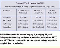
Converting a specified decibel limit to an actual percentage of voltage magnitude that is coupled, lost, or reflected in a given application can simplify comparison of actual performance benefits by different category-rated components. Keep in mind that the comparison method applies to all component and cabling-system claims.
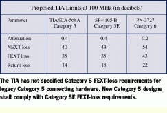
It`s also important to note that the decibel function can prove misleading when comparing performance data. For example, an 8-dB improvement in connecting-hardware return loss (from Category 5 to Category 6) results in a 60% drop in reflected signal voltage, while a 14-dB improvement in connecting-hardware NEXT performance (also from Category 5 to Category 6) results in an 80% drop in coupled signal voltage.
Decibel values and performance-headroom claims
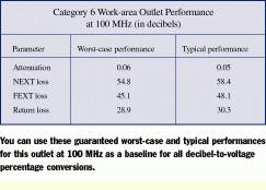
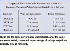
Performance claims in decibels may also be converted to a voltage percentage lost, coupled, or reflected for any cabling product or system. Let`s look at an example of such a conversion using the typical and worst-case performance claims for a commercially available Category 6 work-area outlet. The example shows that a worst-case 0.06-dB attenuation performance converts to 0.7% of the signal being lost, while a typical 0.05-dB attenuation performance converts to 0.6% of the signal being lost. Similarly, 54.8-dB worst-case NEXT loss and 58.4-dB typical NEXT loss convert to 0.2% signal coupling and 0.1% signal coupling, respectively. A 45.1-dB worst-case FEXT-loss and 48.1-dB typical FEXT-loss claim converts to 0.6% and 0.4% signal coupling, respectively. And 28.9-dB worst-case and 30.3-dB typical return-loss performance convert to 3.6% and 3.1% signal reflection, respectively.
One of the advantages of comparing data on a percentage-voltage basis is that signal-performance margin is independent of the normalizing tendency of the decibel function. For example, the aforementioned work-area outlet`s worst-case return-loss performance of 28.9 dB calculates to a 6.9-dB margin over the Telecommunications Industry Association`s (TIA--Arlington, VA) performance limits, but its performance actually delivers more than a 50% drop in reflected signal voltage compared to the limits.
Understanding the decibel function can provide additional insight into performance claims. In addition to reviewing specific frequency points of interest, note that an important aspect of complete component qualification includes knowledge of worst-case performance specifications and margins guaranteed over the full category frequency range of interest. Furthermore, always be sure to look for linear frequency response in addition to worst-case values when analyzing performance data.
Converting decibel claims and margins to percentage voltage loss, coupled, or reflected can provide meaningful insight into the magnitude of a manufacturer`s performance claims.
Valerie Rybinski is a senior electrical engineer with the Siemon Co. (Watertown, CT). She chairs the TR-42.7.1 Copper Connector Working Group of the Telecommunications Industry Association (TIA) and is secretary of the TIA`s TR-42.7 Copper Systems Subcommittee. A more technically detailed version of this article with additional figures and equations is posted on the Siemon Co.`s Website at www.siemon.com.
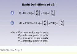
These definitions of the decibel function allow you to plug in manu-facturers` performance claims and convert them to percentage volt-age lost, coupled, or reflected.
A note about power
Telecommunications decibel limits typically are cross-referenced back to voltage ratios. However, power ratios can be specified just as easily. Substituting 1 volt into the decibel function and solving for the corresponding decibel that relates to half of the signal power (0.5 watts) demonstrates that an improvement in performance by 3 dB results in a reduction in power by one-half. This rule of thumb--that a 3-dB difference equals a 100% performance improvement--is commonly used in the cabling industry.
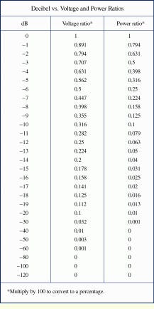
The third column of this table lists the equivalent power loss or drop per 1 watt to which a sampling of decibel values correlates.
