Getting to the core of Category 6 cable
Pair-isolating splines in UTP cables: technological advancement or a return to cabling`s past?
Patrick McLaughlin
Pick up an unshielded twisted-pair (UTP) cable that is designed to comply with the forthcoming Category 6 cabling specifications and chances are you`ll see more than just four pairs of conductors within the outer sheath. Most cable manufacturers delving into the Category 6 arena are including pair-isolating center members--referred to by many as splines--in their products.
"The splines make a big difference in performance, particularly with respect to crosstalk and attenuation," says James Anastasi, director of product engineering for Helix/HiTemp Cables Inc. (Franklin, MA), a Draka USA company and member of the Draka Global Datacom Group. The spline is designed to physically separate the conductor pairs within a 4-pair cable from each other, and in doing so, minimize the disruptive effects that active pairs have on one another.
Different spline designs
Anastasi reports that there are variations among spline designs, including sizes and materials. "Work is still being done to optimize the materials used in the splines," he says.
Scott Stevens, technical services manager with CommScope Inc. (Claremont, NC), reports that few changes have been made to the spline in the company`s UltraMedia product. UltraMedia, introduced in the spring 1998, was among the first UTP products with a spline.
However, you will find some differences from one spline to another. For example, the spline in a plenum cable may be made from a different material than the spline in a nonplenum cable. CommScope is developing a foamed fluorinated ethylene propylene (FEP) spline that uses the same unique technology the company developed to insulate individual conductors. Foamed products can dramatically reduce the size and weight of the cable.
One significant reason that splines have become common in 4-pair UTP cables is that the Category 6 cabling standard will specify performance to 250 megahertz, including positive attenuation-to-crosstalk ratio (ACR) to 200 MHz. When UTP cables carry signals at such high frequencies, each active pair is more likely to have deleterious effects on the surrounding pairs than would be the case at lower-frequency transmission. So even with improved performance characteristics like return loss and improved physical properties like balance, a Category 6 cabling run will be susceptible to pair-to-pair and power-sum crosstalk performance anomalies because of the high frequency range in which signals will be transmitted.
With Category 6 specifications still relatively early in development, using a spline in an attempt to ensure Category 6 compliance for characteristics like near-end crosstalk (NEXT) and equal-level far-end crosstalk (ELFEXT) is the path most cable manufacturers have chosen.
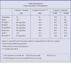
"One current proposal for Category 6 requirements includes a 4-decibel performance improvement over Category 5 for attenuation at 100 MHz, an 18-dB improvement over Category 5 for NEXT at 100 MHz, and a 22-dB improvement over Category 5 for ACR at 100 MHz," says Paul Kish, senior product manager at nordx/cdt (Pointe-Claire, QC, Canada), a Cable Design Technologies company. Kish chairs the TR-42 Engineering Committee of the Telecommunications Industry Association (TIA--Arlington, VA), and nordx/cdt proposed the specifications he refers to. "The other proposal currently in front of the TIA and the ISO [International Organization for Standardization--Geneva] is more lenient and may or may not be achievable without center splines inside cables," reports Kish. "But the requirements in the more stringent proposal cannot be achieved without using splines."
In addition to using a center spline, what are cable manufacturers doing to ensure their products meet the Category 6 specification, once the standard is finalized? Most are tightening up their production processes with respect to characteristics like balance and pair lay. "Balance," says Helix/HiTemp`s Anastasi, "is a fairly simple concept. Essentially, the two conductors that make up a twisted-pair have to be clones of one another. A well-balanced cable helps eliminate residual interference, which can be caused by full-duplex bidirectional signaling. Pair lay also contributes to crosstalk performance," he continues. "Even if the pairs are well-balanced, crosstalk can result from pair lay."
Sounds strangely familiar
One method that can help minimize attenuation, which increases as the frequency increases, is to produce a conductor slightly larger than the 24-American Wire Gauge (AWG) conductor commonly used in Category 5 and Category 5E UTP cables today. "A thicker conductor that`s closer to a 23-AWG can be used to help meet the attenuation requirements proposed in Category 6," says John Pryma, vice president and general manager of Genesis Cable Systems` (Pleasant Prairie, WI) structured cable division. And, Pryma says, the notion of a larger conductor and isolated pairs brings to mind a period that might be called the cabling industry`s infancy--the late 1980s and early 1990s.
Pryma is uniquely qualified to comment on the similarities that some might consider eerie. He was a member of the product-management team at Anixter Inc. (Skokie, IL) when he laid the groundwork for what became known as the "Levels" program, which later was adopted nearly verbatim as the "Category" system by the TIA.
"Consider the situation then," he explains. "Ethernet originally ran on 50-ohm coaxial cable, and Token Ring used 22-AWG, 150-ohm shielded cable." Ethernet ran at a maximum speed of 10 megabits per second, and Token Ring initially ran at 4 Mbits/sec and later achieved 16-Mbit/sec speed. The conductors were relatively large and shielded to ensure network performance. The connecting hardware was complicated compared to the modular plugs and jacks that would follow. But as users increasingly embraced UTP cable constructions, running Ethernet and Token Ring over UTP became a reality.
Now consider the situation today. Ethernet has taken over as the protocol of choice within local area networks (LANs). Many current estimates hold that approximately 80% of today`s LAN environments use the protocol. Ethernet fairly smoothly moved from 10 to 100 Mbits/sec over UTP cabling, with Category 5 cabling capably handling 100-MHz 100-Mbit/sec Fast Ethernet. But, attempting to achieve 1000-Mbit/sec (1-gigabit- per-second) transmission over UTP cabling has created the need to examine some performance characteristics never before considered for the medium. Full-duplex, bidirectional signaling has focused attention on NEXT and FEXT measurements--both pair-to-pair and power-sum--in UTP cabling runs.
In essence, the signaling techniques necessary to run Gigabit Ethernet over UTP cabling at 100 MHz have necessitated the development of the Category 5E standard, which at the time of this writing was in its 11th draft and on the verge of ratification. Additionally, early drafts of the Category 6 standard specify tighter specifications than Category 5E at 100 MHz, mandate positive ACR at 200 MHz, and spell out performance requirements to 250 MHz--two-and-a-half times the maximum frequency of Category 5 and Category 5E.
Category 6`s stringent demands have put cable manufacturers in a position where they are introducing separators (reminiscent of shields) into their products to achieve acceptable performance. Meanwhile, connector manufacturers are developing tuned (some would say "proprietary") plug-and-jack combinations that can only achieve the proposed Category 6 performance requirements when used with one another. Some of these connector manufacturers are also producing more complex hardware to achieve proposed Category 6 performance. And one of the techniques for achieving low attenuation in advanced cabling systems is to increase the size of the conductor--bringing to mind the large 20-AWG single conductor within the 50-ohm coaxial cable over which Ethernet originally ran.
Natural cycle
Genesis Cable Systems` Pryma says the full-circle theory with respect to data communications is not a reason for serious concern. In fact, he points out, it can be viewed as a natural progression, which parallels the path already followed by some other forms of communication. "Look at television broadcasting," he says. "It has gone from wireless to wireline and is going back to wireless. First it was sent out over the airwaves, and viewers had to configure antennas in or outside of their homes for decent reception. Then cable TV put the signal on a wire and brought it into your home and all the way to your TV with clear reception. Now, the trend is shifting back toward wireless, with satellite dishes gaining in popularity, partly because of the picture clarity they provide.
"Telephone communication could undergo a similar transition. It started as a wired technology, but today cellular communication is more popular than ever. However, wireline transmission may become more popular again if an application like the videophone gains a foothold and requires the information- carrying capacity of the wired system."
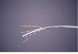
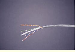
Helix/HiTemp`s SuperCat 1000 cable includes a center spline that separates the twisted pairs from each other. The spline twists throughout the length of the cable to accommodate the lay of the twisted pairs.
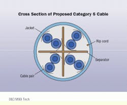
A cross-sectional view of a cable designed to meet Category 6 specifications shows the spline that separates each pair from the others. Some manufacturers have chosen to incorporate 23-AWG conductors into the Category 6 product lines to meet proposed attenuation performance at high frequencies.
The return of proprietary systems?
Initial development of the Category 6 standard by the Tele--communications Industry Association (TIA--Arlington, VA) has caused some concern about the possible end of fully interoperable high-performance cabling systems. When manufacturers of plugs and jacks tune their components to achieve positive attenuation-to-crosstalk ratio (ACR) at 200 megahertz, the side effect can be an incompatibility with other connecting hardware. Likewise, when partnering cable and connector manufacturers will not warrant systems that include components from nonpartner companies, users begin to believe that their choices are limited and some of the highest-performing cabling components available cannot necessarily make up a fully interoperable system.
Because of this concern, the TIA issued a press release last March to clearly state that a key objective of the Category 6 standard is to ensure backward-compatibility and interoperability of all components and mated connections. "Backward-compatibility and interoperability mean that next-generation cabling, components, and mated connections shall satisfy all requirements of their category in addition to all existing lower-category specifications," the statement read. This issue is at the top of the TIA`s agenda in the development of a Category 6 cabling standard (see "Hardware and Category 6 backward-compatibility," August 1999, page 53).
nordx/cdt, developer of one of the Category 6 proposals under consideration by TIA, maintains that its proposal is preferable because it is based on an alternate Category 6 cable with low attenuation and high near-end crosstalk specifications. The chief benefit of using a low-attenuation cable for a Category 6 standard is the ability of equipment developers to make the best use of increased received signal power and higher noise immunity. Additionally, the proposal allows the use of a wider range of jack-and-plug connections that are more likely to be backward-compatible with existing cabling installations, nordx/cdt says.


