An infrastructure based on codes and standards will allow for efficient growth and maintenance.
Mark Stoops / Seitel Leeds & Associates
The term "outside plant" (OSP) originated in the late 1800s. As Alexander Graham Bell's invention grew in popularity and the Bell System was formed, the new company needed to organize its operations into manageable areas of responsibility. These areas were defined as "plant departments." "Inside plant" (ISP) encompassed the switchboards that were later replaced by telephone switching machines we now call central offices. OSP referred to the facilities and all related components from the switchboard to the subscriber's telephone set.
Nearly a century later, AT&T faced a number of legal issues. The final settlement and court orders resulted in the formation of the regional Bell operating companies (RBOCs). At the same time, the Federal Communications Commission (FCC) issued limitations that prohibited RBOCs from manufacturing, selling, owning, or maintaining equipment installed on the customer's side of the service delivery point (the demarcation point, or demarc).
The ruling that ordered AT&T's divestiture also defined the area of responsibility of the telephone company (telco) and that of the customer or building owner. It specified that the telco would be responsible for provisioning service up to the demarc-the dividing line between telco- and customer-owned facilities. However, this issue is complex since the demarc can include facilities in both the ISP and OSP.
The telco has a unique administrative name for each cable pair from its switching center to each demarc. This administrative cable count is maintained in centralized databases in the telco's service centers. In the past, the cable pairs on the customer campus were also given unique administrative names. The cable records for these campus networks were usually kept in the main terminal location on the campus and were maintained by the telco's installers. These cable identifications were referred to as "house counts," and the cables were referred to as "house cables" or "black sheath cables." Eventually, the cable plant that had been installed to support the voice systems on the customer's side of the telco demarc was transitioned from telco ownership and maintenance to customer ownership and maintenance.
Suddenly, customers had to hire cabling installation contractors to perform functions no longer in the telco's jurisdiction. With divestiture, no one took over the responsibility of maintaining the customer's cable records. The house count became open game, and its use can best be described as first come, first served. As the house cables began being used up, it became common for installers to "borrow" pairs to install new service. If dial tone was not found on a pair, it was often considered to be available. (Remember, not all services have dial tone on the pair.) Sometimes, repairs were made by replacing a jumper cable "borrowed" from somewhere else. The outcome was often a mess of cable and jumpers that no one really controlled.
Assess what you own
So just what is this interesting conglomeration of stuff that you, the customer, now own? First some definitions:
- Customer-owned inside plant (COISP) refers to the pathways, spaces, and cable plant providing the interconnection of all low-voltage systems within a customer's building.
- Customer-owned outside plant (COOSP) refers to the pathways, spaces, and cable plant providing the interconnection of all low-voltage systems within a customer's campus.
In COOSP, just as in the telco OSP, there are three environments to consider: aerial, direct-buried, and underground. Aerial infrastructure includes poles, support strand, and guy wires. Direct-buried means the cable plant is in a good old-fashioned ditch. Underground means the plant is underground but housed within vaults and conduit.
Each environment-aerial, direct-buried, and underground-has pathways, spaces, and cable plant. The pathways are the trenches, conduit, and pole lines that the cables run in, on, or through. The spaces are the splice pits, vaults, pole-mounted cabinets, and wall-mounted cabinets where the cable plant is spliced and makes the transition from one environment to another. And of course, the cable plant is the twisted-pair copper, coaxial, and fiber-optic cable.
Let's look further at the telco demarc and the pathways feeding it. The location of the point of demarcation between the telco and customer can vary depending on the regulations in your state, because the FCC rulings mentioned earlier are subject to interpretation. Every telco must provide a demarcation point between itself and the customer. In most cases, this demarcation point is in the first equipment room where the telco cable enters. However, it can also consist of separate demarcation points on each floor of each building in a multibuilding campus, or a single demarcation point at the first point on the edge of the property where the cable crosses the property line, or other similar arrangements.
In many states, telcos have a tariff in place that addresses the customer-provided entrance path. When a property is developed, the telco will require the property owner to provide a path for the installation of the telco's facilities. Typically, that will entail one or more buried conduits (with associated pullboxes), pullstrings, a backboard in a secure space, electrical outlets, and a connection from the backboard to the building service electrical ground. The telcos are good about telling customers that they are required by the tariff to provide this equipment. But they typically don't do a good job of explaining to customers that once the telco installs cable in the conduit, according to the terms of the tariff, the telco takes ownership of the conduit. Furthermore, the telco's ownership gives it the right to ban others from using the path.
When you are designing entrance facilities, it is highly recommended that you provide separate entrance paths for each communication provider from whom you expect service. When considering entrance paths, you should also plan multiple paths to provide for route diversity. In today's environment, your networks and their access to the public network figure heavily in your business's critical process path. Installing diverse entrance paths now will allow you to implement network diversity later without having to tear up the parking lot twice. This is also a good time to familiarize yourself with the codes and standards you must follow when designing and installing your OSP (see "Making your outside plant standards-compliant," page 44).
Identify everything
To get a handle on your COOSP and be successful in its maintenance and expansion, you first have to identify what you own. Your building owner or plant-management department can provide copies of the site plans for the property showing the buildings and site improvements. You will also need floor plans for all the buildings and the electrical drawings for the site and buildings. Last-and likely the most useful, if you can locate them-are the old telco maps and cable records for your facility. At larger sites, it is common to find the original telco map taped to a wall in the main terminal room. Cable-assignment records will be more difficult to locate, but again, finding them is worth the effort. If you find these documents, you should guard and protect them. They most likely no longer exist anywhere else.
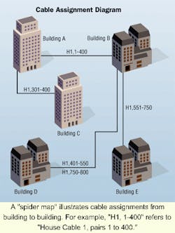
Now that you have these tools, what are you going to do with them? Your goal is to develop a set of cable maps and cable- assignment records. To manage, maintain, move, add to, and at times remove these cables, you need to know in as much detail as possible what type of cable they are, where they are, and how they are being used. First, you must identify the type, size, and quantity of cables and conduits leaving the entrance facility room of each building. The cable-identification information on the cable protectors and crossconnect fields will tell you where the other end of the cables are. At this point, you can begin building a cable "spider map." You may use a simple diagram using blocks to represent the buildings. A good starting point is working from the architectural site plan or the electrical site plan.
If you are in Building A looking at the main cable termination field and you see something like "H1 pairs 301-400 to Building C," draw a line from Building A to Building C on your diagram and label it "H1, 301-400." Continue your search from building to building until you have included all the cable pairs in your diagram.
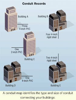
While you are making notes about the cables leaving each building, it is advisable to also note conduit information, including type, size, quantity, and direction of travel. This information could be a bit more difficult to obtain. A conduit might leave the entrance facility room through the ceiling and wind up leaving the building through the basement wall.
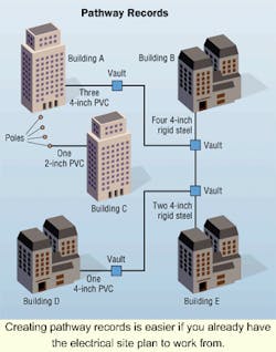
The next step is to review the electrical site plan and the site itself. It is a good idea to use the electrical site plan because it probably already includes the conduit information. In general, you will have better luck if the drawings you are working from are the ones with the construction as-built notes on them. Look for low-voltage conduit systems, pole lines, and trenching that interconnect the buildings. The pole lines will be easy to find. To accurately locate the conduit and direct-buried cable routes, you will need to use a cable locator. Once you finish this effort, you will have your pathway records.
Another type of record you should have is a spreadsheet showing where each cable pair is available for use and where those in use have been crossconnected. In telcos, these were formerly called Exchange Customer Cable Records. They were large metal binders with special columnar sheets showing every cable pair in the exchange, every terminal where each pair was available, the phone number assigned to the pair, and in which terminal it was working. Your spreadsheet will most likely be less complex. You can purchase network documentation tools that can track the physical-layer facilities and are combination mapping and database tools with many options.
Repair, replace, or expand?
COOSP documentation is a helpful tool for the next step: reviewing the age, condition, and use of each cable and conduit. Pay close attention to the condition of the infrastructure and how it is installed. Make sure the cables have the necessary electrical protection to ensure the safety of your fellow employees, the public, and your systems. Check the clearance between your COOSP and other utilities. Once you are sure your COOSP is in good condition, you can decide if you need to repair, replace, or add to it.
Whether you are repairing, replacing, or adding to your COOSP, the first thing you will need is a pathway. If you plan to repair or replace, consider reclaiming existing spare paths before building new ones. You may be able to consolidate services from multiple underutilized cables into fewer sheaths, allowing the removal of cables to create a path. Similarly, you may be able to consolidate small cables in individual ducts into a single duct. If a path cannot be reclaimed, it will be necessary to design and build a new one. At this point, the tendency is to design and build the duct system before the cable network is fully thought out, which often results in undersized duct runs. By designing the cable plant before the duct system that supports it, you can provide spare duct capacity.
Pathways in a properly designed COOSP have a useful life span of 50 years or more. In some telco environments where I have worked, underground cable jobs still use conduit systems built in the 1890s. By contrast, the cable plant interconnecting your buildings will likely need replacing in 15 to 20 years, if not sooner.
Mark D. Stoops, RCDD, is an electrical engineer working for Seitel Leeds & Associates, a Seattle-based voice and data network design firm. He can be reached at [email protected].
Making your outside plant standards-compliant
You, the customer, are responsible for the installation and maintenance of your campus network infrastructure. In the customer-owned outside-plant (COOSP) arena, installing a standards-compliant infrastructure is a huge challenge.
The codes you must consult when designing COOSP are the articles of the National Electrical Code, published by the National Fire Protection Association (NFPA-Quincy, MA). The articles in this code address the protection of life and property. You will also need to meet the requirements of all local building codes, which may include (by adoption) the Uniform Building Code. Remember: Codes address fire- and life-safety issues. They do not provide guidance on how to determine duct bank sizes, cable sheath sizes, or similar technical information.
There are standards in the Occupational Safety and Health Administration as well as the Industrial Safety and Health Acts of individual states that must also be met. More information is available at www.osha.gov and from your state's Office of Labor and Industry.
You would also be well-advised to follow industry-specific standards, which, although not required by law, are considered de facto standards by most people in this industry. These standards are easy to understand, thanks to the efforts of the American National Standards Institute/Telecommunications Industry Association/Electronics Industries Alliance (ANSI/TIA/EIA-Arlington, VA). In particular, ANSI/TIA/EIA-568A and -569A have useful guidelines for installing and maintaining your COOSP.
Two excellent references are BICSI's Telecommunications Distribution Methods Manual (TDDM) and the Customer Owned Outside Plant Design Manual. The TDDM and COOSP Manual, while not standards, are informative and useful reference documents, so many organizations have adopted them as a standard for their installations. More information is available at www.bicsi.org.
In addition to the codes, standards, and reference materials, there are professional service firms that can assist in the design and management of your COOSP. You may want to find a registered communications distribution designer (RCDD) to assist you. Professional designers who have earned the RCDD title have proven, through work experience and an official exam process, that they understand the networking physical layer in great detail. That physical layer is your primary concern in the COOSP area. In addition to RCDDs, you may wish to seek the assistance of architect and engineering firms as well as network design firms.
You or your consultant will use the codes, standards, reference materials, and heuristic knowledge with multiple goals in mind. The goal is to make sure your COOSP infrastructure will have a long, efficient life and meet both the current and future bandwidth needs of your network. In addition, you will address technician and general public safety during construction as well as on a day-to-day basis.


