An old building can be given a new soul, but only after design and engineering are pushed to their limits.
Herb Hauser
Barnes Wentworth Inc.
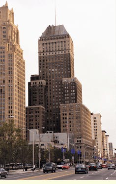
The sun is shining on Newark, NJ. After many difficult years, this once-glorious city is being rediscovered and rebuilt as a business, sports, and entertainment center. This modernization poses a formidable challenge to those charged with engineering new communications infrastructure for Newark`s sacrosanct landmark office buildings.
A central figure in the "Newark Renaissance" is Arthur Stern, chairman and chief executive of Cogswell Realty Group (CRG), who acquired the city`s oldest and tallest office tower: the 650,000-square-foot Newark National Building. This art-deco beauty, built in 1929, is currently being restored to its former glory with one major difference: Newark`s Grand Dame is being outfitted with some of the most advanced and comprehensive technology and communications infrastructure available.
When this $40-million renovation is completed, city officials hope that the Newark National Building will lead the way to restoring Newark as a center of commerce and establishing it as a center of e-commerce.
Soon after purchasing the building, Stern commissioned Barnes Wentworth Inc. to design a communications infrastructure that would carry the building well into the 21st century. As we left the first meeting, he turned to us and said, "I don`t want only wires and cables for this building. I want her to have a new soul and a new mission. I want her to lead the way for other real estate developers who might decide to come to Newark."
In addition to these marching orders, Stern told our group that the communications infrastructure, like the infrastructure for electricity, water, and heating, ventilation, and air conditioning (HVAC), was to be owned and controlled by CRG. Like a handful of other visionary real estate owners and developers, Stern and CRG decided to make the communications infrastructure the fourth utility--as important to the building as the electrical risers, HVAC shafts, and water pipes.
Phase I: Assessing the situation
Randy Levine, vice president of networks and infrastructure at Barnes Wentworth, headed the project. He and his team began a top-to-bottom study of the building and its existing infrastructure. After the surveys and studies were completed, Levine called the design group together and said, "Forget most of what you`ve done in the past, and forget conventional wisdom; just keep in mind tia/eia [Telecommunications Industry Association/Electronic Industries Alliance--Arlington, VA] and IEEE [Institute of Electrical and Electronics Engineers--New York City] specs and prepare yourselves for a trip back to the future."
He then proceeded to outline the following challenges:
For all practical purposes, there were no stacked closets that could be used as intermediate crossconnects.
There was an existing ILEC (incumbent local-exchange carrier) infrastructure that was less than 10% in use.
Any conventional closet-stacking design would result in core drills through the space of existing tenants.
The basement frame room that was built 70 years ago was inadequate for today`s communications needs.
Some of the building`s functioning communications cabling was cloth-wrapped.
The first few floors of the tower function as a carrier hotel, and these businesses could not be disrupted.
The landmark status of the building posed a problem for almost every internal route that was selected for the new infrastructure.
Wireless and satellite receivers could not be easily mounted to the roof because of landmark-status issues.
Although parts of the building were being leased to new tenants, a number of existing tenants required that the infrastructure be designed to accommodate their legacy needs.
In the face of these obstacles, Levine compiled a list of design features that he considered absolutely essential for 21st century communications infrastructure:
The building should be "carrier neutral," offering access to all providers of copper, fiber, and wireless communications and accommodating any future technologies that tenants might want.
The backbone should accommodate both below-grade and rooftop wireless "meet-me" functions, whereby the various telecommunications providers exchange fiber and content with each other.
The riser should accommodate broadband video distribution, from both wireless and subterranean sources.
The building should have a redundant backup riser in a space distinctly separate from the primary infrastructure.
The main crossconnect (MC) in the basement should accommodate the ILEC as well as all competitive LECs that wanted access to tenants.
A crossconnect field should accommodate hand-offs of circuits from the telephone companies to the building patch fields that could be maintained in a well-organized fashion.
A horizontal floor distribution scheme should deliver all capacity the riser offers without violating the landmark status of the building.
The infrastructure should accommodate yesterday`s, today`s, and tomorrow`s communications needs because that`s what the mix of tenants are using or plan to use.
Phase II: The plan
Faced with these challenges, Levine put together an engineering team that was drawn from both internal and external resources. Paul Dugasz and Rob Jablonski from Barnes Wentworth became the lead premises-distribution-systems project manager and engineer, respectively. And because fiber cabling was to be a central feature of the design, Levine interfaced with Marcus Giebel, an infrastructure expert at Siecor (Hickory, NC).
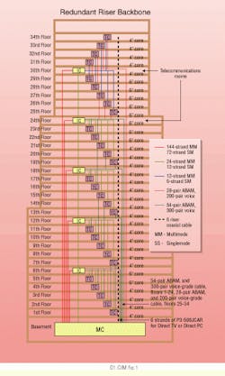
The basic plan was as follows: On the low-rise floors (two to 24), we would install 24 multimode and 12 singlemode strands of fiber, 300 voice-grade copper pairs, 54 pairs of T1 ABAM cable, and a video riser consisting of p3-500jcar coaxial cable. On the high-rise floors (25 to 34), the same mix of infrastructure would be applied, although in smaller quantities. On these floors, 12 multimode and six singlemode strands of fiber, 200 voice-grade copper pairs, 28 pairs of T1 ABAM cable (twisted-pair copper wire that supports T1 transmission speeds of 1.554 megabits per second), and a video riser consisting of p3-500jcar coaxial cable would be installed.
Because of the shape of the building and field conditions present in a comprehensive renovation, the communications infrastructure team found that it was impossible to deliver the desired infrastructure to each floor with a consistent routing design. Levine informed the team that straight cores would result in coring through existing tenant space on some floors and through the center of reception areas on others.
The team went back to work and developed a new, hybrid design. Every floor would have homeruns of voice-grade and T1 ABAM cable from the MC. The fiber plant, on the other hand, would be run to each of five intermediate crossconnects (ICs), which, in turn, would serve the IC floor as well as the five floors immediately below it. The team decided on this design because it minimized the number of copper crossconnects while providing more control over the fiber plant. Moreover, the five ICs were interconnected with a 144-multimode, 72-singlemode fiber trunk. This trunk represented the first level of redundancy.
Unlike most communications risers, the one at the Newark National Building had an additional mission. Stern had anticipated that broadcast video would become increasingly important for most businesses. To address the need for video distribution, the Barnes Wentworth team designed a system that could accept subterranean and wireless (satellite) feeds. A vertical cabling plant was installed so that each IC was supplied by p3-500jcar coaxial riser broadband cable. Moreover, express cables (cable runs that are used to deliver signal from one site to another without interruption) were run from the roof down to the MC so intrabuilding distribution of wireless signals could be achieved. Finally, special railing systems were designed to allow for nonpenetrating roof mounting of satellite receiver dishes. Naturally, these dishes had to be placed behind a parapet wall and be architecturally acceptable so as not to violate the landmark status of the building.
Phase III: Implementation
The routing on the upper floors of the building followed traditional core-and-build design. In this design, we opened 6-inch cores on the floor and built communications closets around them. For the lower half of the building, the team was given access to an abandoned shaft, soon lovingly renamed the "Big Shaft."
Fortunately, Jablonski, our lead engineer, is an avid mountaineer. He rappelled down the shaft, much like a climber descends a mountain, and announced that the interior skin was too weak to sustain any type of superstructure capable of holding the guide wires to which we had planned to attach the cables. No matter how we designed the superstructure, it would be too weak to do the job.
How were the installers going to hang the cables from the guide wires in the shaft if it could not support the superstructure that was supposed to hold the guide wires? The solution came from three additional players: the building`s general contractor, the Bern Companies; Frank Montesano, vice president of operations at Cogswell Realty; and David Lederman of Streetwood Management. In a joint surge of creativity, they redesigned the Big Shaft to accommodate steel I-beams that would hold the guide wire superstructure. In the end, the shaft provided the installation team with clear, safe, and sturdy paths to each floor.
Physical redundancy
While the redundancy plan of the riser was greatly enhanced by running fiber trunks between the ICs, there was still insufficient physical separation between the redundant links and primary riser. Trying to locate the cores for the backup riser proved to be impossible. None of the stacking models that were developed were compatible with existing office and closet spaces on the floors. Moreover, it was impossible to core the hallways because of the building`s landmark status.
During one of the weekly build meetings, it was announced that the mail chute, which ran from the building`s main floor to the top floor, would be abandoned. Upon hearing this, our engineers made some quick measurements and calculations and determined that the abandoned mail chute would provide us with a superb pathway for the redundant fiber. The building owners asked the U.S. Postal Service to decommission the mail chute, and it soon became the redundant riser pathway. Its now blackened glass and polished brass can carry e-mail instead of paper mail--an appropriate end to one era and beginning of another.
Meeting space
Although much of our effort was directed toward the base building infrastructure, the design team had a number of other challenges. The Regional Business Partnership (RBP), a not-for-profit organization, planned to move into one of the high-rise floors. The RBP wanted to make a high-tech conference center that could be adjusted in size to accommodate various groups, yet provide excellent, high-speed wide-area- and local-area-network connectivity. Normally, such a requirement would be handled by standard floor poke-throughs that would distribute both data and power to the area immediately surrounding it.
Unfortunately, standard designs for a modern building do not necessarily work in a vintage building. The floor construction of the Newark National Building was such that most of the floor load was borne by structural steel, meaning that the floor could be made mostly of ash--a material weaker than concrete and not well-suited for multiple core drills. If we were to core in the density needed to provide all the power and connectivity to the space, we would have caused the floor to become "spongy" and, therefore, unsafe.
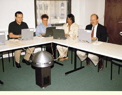
To address this problem, the design team came up with a solution we called "the Mushroom." The device anchors itself into a 6-inch core via a large but simple bayonet fitting. Once attached to the core, the Mushroom then attaches electrically to the power outlet in the center of the core. A similar attachment is made for voice and high-speed data connections. When fully connected, the Mushroom is capable of distributing 40 amps of electricity through 20 outlets located under its head, and 24 high-speed data and 12 voice lines distributed from RJ-45-type outlets located along the perimeter of its cap. After an event, the 24 x 16-inch Mushroom is disconnected, twisted off the bayonet fitting, and stored. The 6-inch core is covered with a flush-fitting, threaded brass plate.
From the beginning, everyone involved in the renovation of the Newark National Building knew that this project was something special. In fact, the building challenged our views of network infrastructure design and opened our eyes to possibilities we had never before considered.
Part of Newark`s urban renaissance, the Newark National Building is undergoing a communications infrastructure overhaul to accom-modate legacy applications as well as current and future needs.
The building backbone includes a redundant trunk of singlemode and multimode fiber-optic cable, as well as voice-grade copper and coaxial cable.
With multiple power, data, and voice ports, the portable "Mushroom" allows large groups to plug in for high-tech conferencing.
Herb Hauser is president and chief executive of Barnes Wentworth Inc., a technology engineering company based in New York City. He can be contacted at (212) 685-1700 or [email protected].


