New parameters for testing optical fiber in premises networks
LANs require industry-wide test methods and updated test equipment to evaluate fiber/connector performance.
Bob Jensen and Seymour Goldstein / 3M Telecom Systems Div.
As adoption of fiber-based local area networks (LANs) continues to grow, there is an urgent need to educate installers about fiber test methods-and to clarify some misperceptions. Premise networks also require new test instruments to ensure the functionality of their fiber cabling.
An estimated 77% of LAN installers currently use the wrong test method in the premises, according to research by 3M. The growth of fiber-based LANs and the rapid deployment of performance-dependent protocols such as Gigabit Ethernet leave little margin for error in the loss budget to accommodate inaccurate test results. Moreover, the move to adopt multi-gigabit technologies is well underway and high-strength fibers are pushing fiber bend radii down to one inch.
Each of these developments highlights the importance of fiber LAN-test accuracy and consistent test practices across the industry. A consensus on testing methods and the effects new application standards such as Gigabit Ethernet will have on test requirements are clearly needed.
Current test methods
A misunderstanding of premises fiber testing is common in the industry because traditional testing of optical-fiber cabling has generally required only attenuation readings to ensure performance. Some specifiers of these systems may also call for optical time-domain reflectometer (OTDR) traces of each cable link.
Given the significance of attenuation testing, it is important to consider the existing cabling test methods. Two test methods are specified for multimode cabling in ANSI/TIA/ EIA-526-14A. The standard specifies these tests as "method A" and "method B." An easy way to remember these test methods and their application is to think of the two approaches as access-provider testing (method A) and buildings testing (method B). These terms offer an easy-to-remember correlation to the standard and provide a descriptor of where these test methods are used.
Traditionally used by telecommunications companies and long-haul carriers, access-provider testing measures the long length of optical fiber where the connector loss is insignificant. Effectively, the cable and splices are tested along with only one of the connections. The test cords and one connection are referenced out. The cable can then be tested once an installer is dispatched to each end of the cable. The test results provide the loss for one connection and the cable. However, when referencing test instruments to this method, a 2% error may occur in the overall results by not taking into account the loss of one of the connectors.
Incorrectly, many installers and specifiers test premises cabling using the access-provider method. Consequently, depending on the reference method chosen in a premises environment, the error level could range from 3% to 25%.
Since new applications require greater accuracy of testing, the buildings test method should be used for these optical-fiber-cabling measurements because the intent of premises testing is to account for the loss imposed by the connections. The buildings test method accounts for two connections-one test cord and the cable under test.
Using this method, one of the test cords is referenced so that the cable can be tested once an installer is dispatched to each end. The referenced cable must remain with the source, and another test cord placed in the test configuration, clean and free of defect. Effectively, the test results provide the loss for two connections and the cable, while the test-cord loss is negligible.
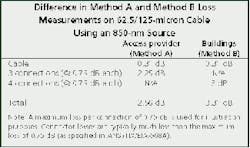
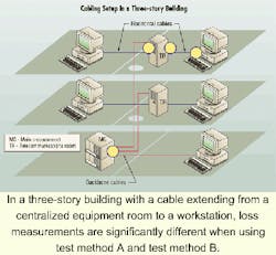
The difference in test results between these two methods is considerable when the outcomes are factored into a loss budget for the entire network. For example, a three-story building with a cable extending from a centralized equipment room to a workstation involves four connections. The access provider method results in a total of three connections incorporated into the loss readings, plus the cable. The buildings test method includes all four connections plus the cable. The table provides the difference in loss measurements when using 62.5/125-micron cable and a source at 850 nm.
In this example, there is a significant difference in the total measurement: 2.56 dB for method A versus 3.31 dB for method B. This discrepancy could be detrimental to the services installed, especially when the channel is used for Gigabit Ethernet. The cabling loss limit as specified in standards for Gigabit Ethernet is 3.2 dB. If this channel were measured using the access-provider method, the loss would seem acceptable. But using the buildings test method, the circuit would not work for Gigabit Ethernet. The different results underscore the importance of determining the proper test method for the application.
The buildings test method provides an accurate measure of the loss in the fiber link by including the cable in addition to all the connections. However, there are some shortcomings to this method related to ease-of-use and testing flexibility.
For instance, it is necessary to disconnect one end of the test cord from the tester when moving to the testing setup from the reference stage. The connection should never be disturbed at the source because the reference is then lost and test results will be seriously compromised without re-referencing. In the transition from the reference setup to the test stage, the test cord could easily be disconnected from the source instead of from the detector end, destroying the integrity of the test. Moreover, disconnecting the test cord from the detector end of the tester increases the risk of damage and of dust or dirt contaminating the detector.
Link performance
To test small-form-factor (SFF) connectors that have the transmit and receive fiber in the same unit, an adaptation to the buildings test is used. This approach overcomes the shortcomings of the buildings test (for use with SFF connectors), provides accurate test results, and preserves the integrity of testing standards.
In this scenario, the test set functions as both a source and meter. The duplex cable and connectors are connected, and a reference is taken. The referencing procedure is actually the same as the one for the access-provider test, using two jumpers. Both test cords plus one connection are referenced in this instance. The cabling can now be tested once an installer is dispatched to each end of the cable. As in the buildings test method, another clean, defect-free patch cord must be placed in the test configuration. Effectively, the test results provide the loss for two connections and the cable. The additional test cord adds negligible loss to the cabling under test. This yields the same outcome as the buildings test method because the results include the loss for two connections and the cable.
This adaptation of the buildings test method, however, does not require the same type of connector on the tester as that which is tested in the network because the two jumpers used for referencing allow for the use of hybrid patch cords.
Consequently, this test method provides the flexibility to test fiber links with any type of connector, regardless of the connector on the tester. While this test procedure is a modification of the TIA-568A test recommendation, it is the approach endorsed by SFF connector manufacturers for the testing of SFF connector links.
Other testing considerations
When specifying test criteria in a cabling project, proper documentation is needed, and the appropriate test method should be indicated. Bidirectional testing is an important requirement when testing backbone cable. While this may not be necessary for testing horizontal cabling, the tests should be conducted in the direction of transmission. Other testing considerations include the following variables:
- Point-to-point identifiers and direction of the test (e.g., outlet number to telecommunications room number).
- Wavelength.
- Test method used.
- Manufacturer, model number, serial number, and date of last calibration of the test instruments.
- Date of testing.
- Person conducting the test.
- Application standards checklist.
Test instruments for the premises
The premises market requires updated test instruments to address new applications and the needs of users. These instruments should be fast, durable, handheld units that are intuitive to the technician. Most of the OTDRs available for use in premises networks are large, a drawback hopefully remedied in next-generation equipment. OTDRs and source and power meters should also have a familiar feel and software to reduce training time. Documentation is important as the software needs to incorporate cable-management utilities and be downloadable to cable-management software packages. Similarly, a power meter should automatically provide a zero reference on every test.
The capability to measure specific parameters with both a light-emitting diode and a vertical-cavity surface-emitting laser to verify Gigabit Ethernet performance is another requirement. Since OTDRs are used in troubleshooting, a visible light source embedded in the unit will also work to the installer's advantage. While OTDRs must continue to measure fiber length as well as the location and severity of events, the results need to be shown graphically-with an automated adjusting of the trace on a screen and in a table format.
What's required
Testing requirements for fiber-optic cabling continue to change. As a result, new procedures and test equipment are needed for premises cabling. The test equipment should accommodate both the access-provider method and the buildings approach. The latter approach-method B-specified in ANSI/TIA/EIA-568A, is the preferred testing method for buildings, or premises networks. However, an adaptive approach using an additional test jumper is recommended for testing SFF connectors and for testing cabling setups involving different connector types. With greater awareness of this test methodology, accurate measurements of link performance for Gigabit Ethernet or multi-Gigabit over fiber can be ensured.
Bob Jensen, RCDD, works for 3M Telecom Systems Div. (Austin, TX) as the technical-services team leader for Volition Network Solutions. He is an active participant in TIA TR-42 and its subcommittees and working groups. Seymour Goldstein is a product-development specialist for 3M Telecom Systems Div. He is responsible for the development and commercialization of various types of fiber-optic test equipment.
This article originally appeared in the April 2000 issue of Lightwave magazine, a sister publication.

