Advancements in technology have made the inspection process more efficient and user-friendly.
By Maury Wood, AFL
The apparently insatiable public demand for broadband internet access, driven largely by widespread on-demand video streaming, VR augmented learning proliferation, and high-resolution image social media sharing (among other rich data-type use cases) is driving data centers to adopt both denser fiber cabling architectures and transmission equipment offering higher speed optical Ethernet standards. With 12-fiber MPO cables (with each fiber carrying 100-Gbit/sec data traffic by 2020), the enterprise value of even a single MPO link is so high that data center operators are now realizing that maintaining absolutely pristine connectors is an operational imperative.
Serendipitously, fast wide field-of-view (i.e. non-mechanical scanning) MPO inspection systems, with IEC 61300-3-35 standard-compliant auto-analysis performance of about one second per fiber, are just now coming onto the market in the second half of 2018. These new rapid multifiber inspection systems hold the potential to overcome the previously held concern in the datacom industry that 100 percent connector inspection, even in hyperscale/hyperdense network infrastructure facilities, is impractical from an operational expense (opex) perspective. This notion is now obsolete, as substantiated by the industrial, economic, and technological dynamics outlined in this article.
The FOCIS Lightning MPO fiber inspection system from AFL offers an instantaneous composite view of the entire endface, up to two rows of 16 fibers.
Lots of fiber, and MPO’s emergence
Modern hyperscale data centers use hundreds of thousands of individual optical fibers, typically spanning tens of thousands of miles in accumulated length, linking compute servers, storage servers and different layers of switches and core routers. The high-speed serial optics found more commonly in telco networks have evolved into higher-speed short-reach parallel optics in data centers. Grouping these parallel transmit and receive optics in multifiber cables and connectors has become best practice. The MPO connector (IEC-61754-87; TIA-604-5 FOCIS 5) and the compatible MTP® connector from US Conec, have emerged as the most popular multifiber datacom-oriented connector types.
One of the practical considerations that has enabled data center MPO trunk cables to proliferate is the recent availability of ribbon (or mass) fusion splicing machines.
Bluetooth-connected ribbon fusion splicers such as this can splice up to 12 fibers simultaneously in about a minute. This level of operating throughput makes the installation and maintenance of highly parallel multifiber cabling practical and cost effective, even in the cost-sensitive data center industry segment.
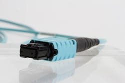
AFL’s FUSEConnect®, shown here, is an example of a 12-fiber connector. Many fiber-networking configurations use only a subset of the fibers available in an MPO connector.
MPO connector characteristics and complexities
MPO connectors, unsurprisingly, are available with both multimode fibers (typically with flat ferrules) and singlemode fibers (typically with angled ferrules). While this article is not intended to be a tutorial on MPO connectivity, there are elements of MPO cabling that should be carefully noted, as they bear directly on the feature sets found in emerging fast MPO inspection tools.
- MPO connectors mate with pins (male or jack configuration) and holes (female or plug configuration). It can be helpful to view at least some portion of the pins and holes with a fast MPO inspection tool, as some industry experts believe that contamination (such as dust) can migrate from the benign pins and holes to the all-important individual fiber ends over time, in a mechanism thought to be caused by fans and other local sources of vibration.
- There are now both MPO-12 (12-fiber) and MPO-16 (16-fiber) connector standards. The MPO-12 key is symmetrically aligned to the connector shell, while the MPO-16 key is asymmetrically aligned to the connector shell, to physically prevent cabling errors. A fast MPO inspection tool that can handle both types (either with different-position keyed adapter tips or “keyless” adapter tips) is helpful.
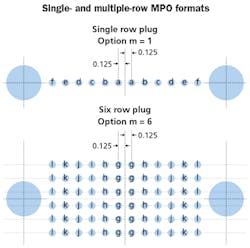
- Worldwide technical standards committees (specifically the IEC, the IPC, and the TIA connector subcommittees) have defined MPO connectors with up to 6 rows (72 fibers for MPO-12 and 96 fibers for MPO-16), so fast MPO inspection tools should be able to scale to 6 rows with 16 fibers per row with firmware upgrades. Note that neither MPO-16 nor arrays larger than 2 rows have proliferated extensively in commercial data centers as yet. The impetus for MPO-16 came from the early days of the IEEE 802.3bs 400G project, which defined 400GBase-SR16 for 100-meter-reach multimode applications using 25-Gbit/sec NRZ signaling per fiber (25 Gbits/sec x 16 fibers x 2 for TX/RX duplex = 32 parallel fibers). More recent 400G physical layer specifications focus on “100G single lambda” methods using PAM-4 modulation, reducing the parallel fiber count to a more manageable count of 8.
- While some pluggable optical transceiver modules use MPO connectors (such as popular QSFP28 100GBase-SR4 type), many others use duplex LC connectors, so MPO-to-duplex LC breakout cables are common in the industry. As such, a fast MPO inspection tool that also offers a single fiber inspection coupler or adapter option for LC and duplex LC connectors can be valuable.
- MPO is a keyed connector, which establishes an unambiguous fiber numbering convention. The MPO connector is said to be “key up” or “key down” in any particular application. MPO adapter sleeves, which enable MPO connectors to be mated, are either “key up, key up” (referred to as “aligned”) or “key up, key down” (referred to as “opposed”). A fast MPO inspection tool that has an easy method for the user to record key orientation is helpful to avoid network polarity problems.
- MPO connectors are typically full duplex in application, meaning that half of the fibers are used for transmit (TX) and the other half of the fibers are used for receive (RX). Obviously, it is critically important that, for example, the TX fibers on a compute server are connected with the RX fibers on a top-of-rack or end-of-row Ethernet switch. Typically, data center operators manage this critical polarity challenge by adhering to one consistent cabling scheme across their data center network equipment infrastructure. According to the TIA-568 specification for MPO cabling, there are three methods of polarity management—Method A (straight through), Method B (mirror reverse), and Method C (pair reverse). Multifiber cable polarity is a complex subject beyond the scope of this article, but suffice it to say that a fast MPO inspection tool that assists users with polarity management (at the facility level) is beneficial. Cloud-based platforms, which have persistent and nominally incorruptible data storage attributes, can be ideal in this regard.
- There are numerous MPO active fiber configurations for which only a subset of the fibers available in an MPO connector are used. One familiar example is referred to as “Base 8” or “Radix 8,” in which the center 4 fibers (which may or may not be populated) of an MPO-12 connector are unused. An example application of Base 8 is 40GBase-SR4, illustrated in this article. 100GBase-SR also typically uses Base 8 cabling. Another example MPO active fiber configuration is “Base 10,” in which the 2 fiber positions on the end of an MPO-12 connector are unused. Fast MPO inspection tools that include support for all commonly occurring MPO active fiber configuration is advantageous, so that “dirty” fiber ends associated with unused fibers do not cause the MPO connector to fail auto-analysis inspection assessments (the dreaded “false negative” problem). Note that some expert users prefer to assess all fibers, in the belief that adjacent contamination can migrate over time to active fibers.
Hyperscales’ overwhelming need for speed
Previous generations of MPO inspection systems used manual mechanical stages to pan (x axis) and scan (y axis) these relatively large-area ferrule endfaces. Systems such as the AFL FOCIS Flex take about 10 seconds per fiber end, or about 120 seconds for a typical 12-fiber MPO connector. New fast MPO inspection systems such as the AFL FOCIS Lightning take about one second per fiber end or about 12 seconds for a typical MPO connector—one full order of magnitude faster. It is rare to see such a dramatic productivity enhancement from one generation of a tool to the next. With a typical hyperscale data center comprising tens of thousands of connectors, this dramatic order of magnitude acceleration in inspection productivity moves 100 percent connector inspection from “too slow and too expensive” to “must have,” particularly when combined with the higher-speed, lower-noise-immunity characteristics of PAM-4-based 100G single-lambda transport technologies, expected to support 200G, 400G and eventually 800G per MPO-terminated trunk cable by 2020.
In Base-8 and Base-10 configurations, some fibers within the 12-fiber MPO connector are left unusued. If these unused fibers are dirty, they may cause a “false-negative” problem, in which the connector fails inspection even though the contaminated fibers will not affect signal transmission. Some users prefer to assess all fibers, based on the belief that over time contamination can migrate to adjacent fibers.
It is productive to roughly estimate the asset value of a single MPO link in order to gain some insight into the economic imperative for pristine (100 percent cleaned and inspected) hyperscale data center connectivity in the 2020 era.
Assuming 100 Gbits/sec per fiber strand (either 2-wavelength 50G WDM or 100G single-lambda by 2020), there are a couple of short-reach datacom options for duplex 400G on a single Base 8 MPO terminated cable: IEEE P802.3cm 400GBase-SR4.2 is a recently proposed multimode fiber example; IEEE 802.3bs 400GBase-DR4 is an older singlemode fiber example. These are both PAM-4 based port types. At equivalent bit rates, PAM-4 modulation requires 9.6 dB additional optical signal-to-noise ratio to achieve the same symbol error probability as the older NRZ modulation method used in 8-fiber 100G links. Amidst this shrinking link budget technology trend, data center managers should carefully note that a single 1-micron-diameter particle of dust results in about 0.1 dB of additional connector insertion loss. With insertion loss budgets tightening with ever-higher line rates there simply is no performance margin for dirty connectors in the 2020 hyperscale data center.
If we assume that broadband subscribers in 2020 will demand 1-Gbit/sec home or business service, a 400G link is carrying the capacity for 400 subscribers with no statistical undersubscription (a highly conservative model that reduces the estimated 400G link asset value). In the United States, it is not uncommon to pay $100 per month for gigabit fiber-to-the-home broadband service, or $1200 per year. Using these estimates, simple math puts the rough asset value of an MPO-terminated 400G link at US$480,000 per year. A highly conservative undersubscription ratio of 1:2 puts the rough asset value per 400G link closer to $1 million revenue per year. The value proposition for an inexpensive fast MPO inspection is very compelling based on this sort of rough cost/benefit analysis.
Capex versus opex in the data center
The financial model of a hyperscale data center is obviously heavily capital-intensive. However, once the equipment is capitalized and depreciated, the model shifts to operational intensity. For turn-up and maintenance operations, a tool that protects and preserves highly valuable assets (e.g., an inspection tool that assures contaminated multifiber connectors will not degrade network physical layer performance) and is productive enough to avoid high opex costs is compelling. Here are two important facts in this regard: 1) A 2002 NTT-AT study found that up to 85 percent of failures in optical networks are caused by contaminated connector endfaces; and 2) In 2016, the Ponemon Institute and Emerson Network Power reported that the average cost of a data center outage is about $740,000.
Standards bodies have specified MPO connectors with up to 16 fibers per row and up to 6 rows per connector. Though neither MPO-16 nor arrays larger than 2 rows have proliferated, nonetheless a fast MPO inspection tool should be able to scale at least 6 rows with 16 fibers per row.
To summarize the desirable aspects of a fast MPO inspection system beyond baseline specifications, the ideal should exhibit the following features andcharacteristics.
- Be small, light and ergonomically designed for ease-of-use with support for both exposed ferrule (i.e. patch cord) and bulkhead (or socket or patch panel or receptacle) inspection. (Either MPO alignment sleeves or female-type “plug-in” adapters are adequate for patch cord inspection, with the mechanical precision [no stacked tolerances] of female-type adapter tips preferred)
- Offer a composite view of the entire MPO connector endface, highlighting passing and failing fiber ends, while providing an optional zoomed-in detailed view of the individual fiber ends
- Affordable, ideally less than $5000 single-unit list price for a full-featured kit with adapter tips and accessories
- Provide easy connectivity to Windows-based reporting software over USB, to mobile apps (both iOS and Android) over both Bluetooth and WiFi, and to a cloud-based workflow management platform for data robustness and ultrahigh availability
- Support UPC and APC ferrule inspection with appropriate adapter tips
- Provide at least partial visibility of MPO pins and holes with a wide field of view (FoV)
- Support inspection of both MPO-12 and MPO-16 connectors with up to 6 rows of fibers
- Support objective (auto-analysis-based) single-fiber inspection of LC and duplex LC connectors
- Support easy recording of MPO connector-key orientation to enable easy management of facility-wide cabling polarity, ideally using a cloud-based workflow management platform for high availability and remote management capability
- Support all common MPO active fiber configurations, including Base 8 and Base 10, to avoid false-negative pass/fail results
- Support the reporting of MPO connector inspection ideally with PDF file generation for multi-platform file compatibility for documentation and invoicing purposes—cloud-based platforms are superior in terms of robustness and reliability
- Support the transfer of images and data to other fiber-optic test instruments, such as OTDRs and loss test sets, so that inspection results can be merged with test results for comprehensive reports
Multifiber inspection solutions with these characteristics will provide many years of service for enterprise and hyperscale network operators.
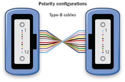
Polarity Method B, one of three standardized polarity methods, employs the mirror-reverse configuration shown here. An MPO inspection tool that can assist users with polarity management is beneficial.
In conclusion, fast multifiber connector inspection using new tools is now feasible even for hyperscale data center operators, with compelling operating expense reduction. Fast MPO inspection should be used by data center technical personnel, not only for maintenance operations, but also for turn-up operation, to ensure that infrastructure equipment and structured cabling is perfectly clean and will not degrade the optical signal to noise ratio across even short links. Fast MPO inspection systems meeting all end customer requirements are now available. The dramatic order of magnitude time savings associated with these systems suggests that previous notions around the economic (opex-oriented) feasibility of 100 percent data center connector objective auto-analysis-based inspection must be seriously reconsidered.
Maury Wood is senior product line manager for inspection products with AFL’s Test and Inspection Division.


