Standards bodies the world over are more willing than ever to coordinate their efforts.
Alan Flatman,
Lan Technologies
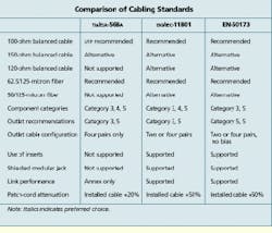
There are a number of significant technical differences between published standards for structured cabling. These differences fall into two main groups: implementation and performance.
Implementation differences represent regional preferences for building the cabling model and should not present any compliance problems. Certain implementation options may limit the applicability or life expectancy of the installed cabling, but these tend to be obvious--for example, the 2-pair outlet configuration.
Performance differences are potentially serious, however, because they may render certain applications non-standards-compliant. Historically, the U.S. structured cabling standards bodies--the Telecommunications Industry Association and the Electronic Industries Alliance (tia/eia--Arlington, VA) have adopted a "component-up" approach to design, whereas international, European, and Australian standards bodies have followed a "channel-down" approach based on the transmission requirements of applications. Ironically, application groups such as ieee 802 and the atm Forum have gravitated toward the tia/eia-568a Commercial Building Telecommunications Cabling Standard, due to its unique channel definition and the availability of a field-testing specification, telecommunications systems bulletin tsb-67. Strictly speaking, therefore, non-U.S. standards are unable to support 155-megabit-per-second non-return-to-zero-encoded Asynchronous Transfer Mode (atm) and the emerging 1000Base-T Gigabit Ethernet. In practice, however, suppliers generally use the same components and field testers, so the problem is not acute.
Nonetheless, these differences underscore the need for harmonization of structured-cabling standards worldwide.
International standard
An international cabling standard was initiated in 1990 and developed by iso/iec committee sc25/wg3 of the International Organization for Standardization (iso) and International Electrotechnical Commission (iec), both of Geneva. iso/iec-11801, Generic Customer Premises Cabling, was published in August 1995. Fifteen nations participated in this project: Australia, Belgium, Canada, Denmark, Finland, France, Germany, Holland, Italy, Japan, Norway, Spain, Sweden, the United Kingdom, and the United States.
The U.S. cabling standard at the time, eia/tia-568, was used as the basis for this international standard, as were the U.S. telecommunications systems bulletins for higher-performance twisted-pair cables (tsb-36) and connector hardware (tsb-40a).
iso/iec-11801 defines cabling infrastructure with a life expectancy of at least 10 years. It has been written for cabling suppliers, end-users, building professionals, and application groups, and it is designed to support local area network (lan) and telecommunications services within a building or campus. The standard covers all aspects of cabling and connector hardware between and including the telecommunications outlets. Strictly speaking, work-area cabling is beyond the scope of the standard, however it provides some useful guidance.
iso/iec-11801 offers two different approaches for implementation--one is based on standard components, and the other is based on link performance. The component-based approach is modeled on eia/tia-568, with specified cable options and maximum lengths defined. Cables and end-to-end distances are not defined for the link-performance approach--these are left for the designer.
Component-based performance
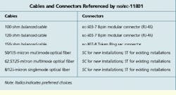
Cables and related connectors referenced within iso/iec-11801 are specified as installed cabling-link requirements; actual component specifications are contained in other iec standards. Preferred choices include the use of 100-ohm balanced cable and 62.5/125-micron multimode optical fiber.
Three levels of performance--Category 3, 4, and 5--are specified for 100- and 120-ohm cables. The construction of these cables is not specified, so they may be twisted-pair or star-quad, screened or unscreened.
iso/iec-11801 also defines Category 3, 4, and 5 levels of connector hardware performance. The standard states that if cable and connector categories are combined within a link, the overall performance will be as good as the lowest-performing component.
The iec-603-7 8-pin modular connector is specified for use with both 100- and 120-ohm balanced cables. The 150-ohm balanced cable is ibm Type 1 screened twisted-pair (as defined in tia/eia tsb-53). The associated media interface connector (mic) is already defined for Token Ring attachment, as specified by iec-807-8.
Two optical connectors are specified: SC and ST. Their application depends on the status of the cabling installation. If ST connectors already are used, then their continued use is allowed. In a new installation, SC connectors shall be deployed, with the duplex version of the connector used at all outlets.
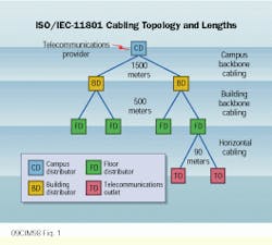
In a campus, buildings may be interconnected with up to 1500 meters of backbone cable. Optical fiber is recommended for this application for bandwidth and safety reasons.
Within a building, each floor or defined cabling zone is then interconnected with up to 500 meters of backbone cable. Once again, optical fiber plays a key role, but twisted-pair copper cables also may be used.
For horizontal cabling, the predominant medium is balanced copper pairs, which may be up to 90 meters in length. Work-area cables, equipment cords, and patch cables in the floor-distributor systems are permitted to increase the overall length to 100 meters.
Link-based performance
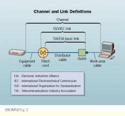
iso/iec-11801 defines a link as all cable and connector hardware between and including outlet, distributor, and patch cord. Its definition of a channel includes equipment cable and work-area cables.
The standard recommends that the combined length of equipment cable, patch cords, plus work-area cable not exceed 10 meters. Actually, its performance should be no worse than 10 meters of installed cable, and it should be noted that flexible cords are allowed to have 50% greater attenuation to accommodate small-diameter stranded conductors required for screened flexible cables. Larger-diameter stranded conductors are generally used for unscreened flexible cables, which typically have 20% greater attenuation.
This link-performance approach was developed to facilitate custom-made cabling solutions, which may be beyond the scope of the component-level specification. However, these parameters for cabling links also form the basis of conformance tests for newly installed cabling as well as tests that validate the suitability of existing cabling installations for supporting high-speed networks such as 100-Mbit/sec Ethernet and 155-Mbit/sec atm.
The link-performance specification in iso/iec-11801 has several application classes to facilitate optimum design. These are as follows:
Class A--links specified to 100 kilohertz for speech bands and low-frequency applications
Class B--links specified to 1 megahertz for medium-bit-rate data applications
Class C--links specified to 16 MHz for high-bit-rate data applications
Class D--links specified to 100 MHz for very high-bit-rate data applications
Optical class--links specified above 10 MHz with high levels of security or noise immunity
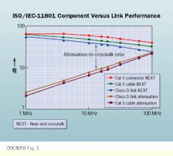
A graphical comparison of Category 5 components and Class D links shows that Class D link attenuation takes account of connector losses and therefore is slightly higher than the attenuation of Category 5 cable per se.
Class D near-end crosstalk (next) takes account of connector crosstalk and is therefore slightly lower than Category 5 cable per se. It also takes account of the next contributions from outlet, distributor, and equipment connectors, which are aggregated using square-law summation.
The attenuation-to-crosstalk ratio (acr) is shown as the difference between Class D link attenuation and next. But it should be noted that iso/iec-11801 specifies additional requirements for acr that are slightly greater than the figures calculated from worst-case attenuation and next. This additional acr requirement accommodates 0.6-millimeter quad constructions, which have lower attenuation but increased next.
iso/iec-11801 requires a minimum of two telecommunications outlets per work area. The outlets should be collocated and are expected to serve approximately 10 square meters. The configuration is as follows:
Outlet 1 with 100- or 120-ohm cable (100-ohm preferred); Category 3 or higher cable; link performance may be Class A, B, C, or D.
Outlet 2 with 100- or 120-ohm cable (100-ohm preferred); Category 5 or higher cable; link performance may be Class A, B, C, or D. Alternatively, 150-ohm cable or optical fiber (preferably 62.5/125-micron) may be used.
Where 100- and 120-ohm balanced cables are used, two or four pairs are attached to each outlet. The provision of four pairs has the advantage of fully populating the 8-pin modular connector and providing maximum bandwidth and functionality cost-effectively. The use of 4-pair signaling is planned for 1000Base-T Gigabit Ethernet and is also required to support high-speed lan applications such as 100Base-T4 and VG-Anylan. The standard therefore requires that the outlet be labeled appropriately if fewer than four pairs are connected.
The use of inserts (for cable pair-to-connector pin reassignment) is permitted at an outlet, but once again the interface offered to the end-user must be clearly defined by appropriate labeling. It should be noted that pair reassignment will be necessary for 2-pair configured outlets when supporting applications that use pins 1, 2, 7, or 8 of the modular connector (such as 10Base-T, 100Base-TX, 100Base-T2, twisted-pair/physical media-dependent [tp-pmd], and atm).
Integrated Services Digital Network pair convention is specified for the 8-pin modular jack, although the individual wires are not, so care must be taken to match both ends (individual wires are generally color-coded). eia/tia-568 outlet wiring conventions T568A and T568B have not been adopted by iso/iec-11801.
The European standard
At the European level, cenelec, the European Committee for Electrotechnical Standardization (Brussels), adopted a draft version of iso/iec-11801 as the basis of a regional cabling standard. The European standard, EN-50173, Information Technology: Generic Cabling Systems, was published in August 1995.
EN-50173 references European rather than international component standards, and informative reference is made to European cable specifications developed by cenelec rather than those being defined by the iec. One example is EN-50167/8/9, which refers to screened Category 5 cables with a low-smoke zero-halogen sheath. This reference is simply an example of a type of cable that may be suitable, but unscreened and polyvinyl chloride-sheath cables may also be used as long as they meet the performance requirements of EN-50173. This is a contentious area because some European nations believe that screened cables are necessary to comply with the new European emc Directive.
One important aspect of European standards is that they must, by law, be used as a basis for all public procurement exceeding approximately US$50,000 in value.
To reinforce their content, all conflicting national standards (which may be internationally sourced) must be withdrawn soon after the national publication of cenelec standards, which are translated without technical change.
Field testing of copper cabling
The tia/eia established a working group in early 1994 to develop a specification of link performance for field testing of unshielded twisted-pair (utp) cabling systems. Specifications were published in October 1995 as tsb-67. This bulletin specifies test instruments, test methods, and minimum transmission requirements for 4-pair, 100-ohm utp cabling links used in high-speed lan applications. This approach is modeled on the link-performance specifications embedded within iso/iec-11801, although different reference points are used for measurement.
tsb-67 includes pass/fail criteria plus a number of sanity checks (such as end-to-end wire mapping). To facilitate comparison of results from various field testers, laboratory pro- cedures and test setup are also described for measuring link performance.
Two test configurations are identified by tsb-67: channel and basic link. The former definition is replicated in tia/eia-568a, Annex E. Implementation of the channel comprises up to 90 meters of cable between the outlet and crossconnect plus a total of 10 meters for work area, patch cords, and equipment cords. It`s important to note that the end connections are excluded from the channel definition; special test connectors are defined for the purpose of measurement.
The link extends from the outlet to the horizontal crossconnect. Both outlet and crossconnect are included within the link. Special 2-meter test leads are defined to facilitate test-equipment connection at both ends.
Test instrument accuracy is specified up to 100 MHz for two levels:
Level 1 relates to the general accuracy of existing (pre-1994) handheld field testers.
Level 2 is a more stringent specification agreed upon by field-test equipment manufacturers for current-generation testers.
Field-test specifications are being developed in Europe as part of the emerging planning and installation standard for cabling, EN-50174, and also at the international level as part of iso/iec-14763. Test specifications for copper cabling are based on tsb-67, but they relate to link class rather than component category.
It`s possible to calculate channel parameters for the link-based scheme by adding the contribution of equipment and work-area cables to the link specification contained in iso/iec-11801 (similar to specifications in EN-50173). tia/eia-568a requires 2 decibels better next at 100 MHz, although this requirement is largely offset by additional requirements for acr specified by iso/iec-11801.
Amendments to international standard
Some short-term technical amendments have been proposed for iso/iec-11801. For channel specifications, it has been proposed that the tia/eia-568a, Annex E, definition be adopted to provide explicit support for atm and Gigabit Ethernet.
In the measurement link specification, it is proposed that the existing "link" be replaced by a "permanent link," hence omitting the crossconnect from the measurement. Test cords are to be part of the test equipment, therefore permanent link values will differ very slightly from the tia`s "basic link."
It`s also proposed that acr measurement be simplified by withdrawing support for alternative next values relating to 0.6-mm quad cables. acr therefore would become next minus attenuation, as it is in tia/eia-568a.
In the horizontal-channel implementation, performance limits for total cordage plus optional crossconnect and transition point would be specified by channel minus permanent link. Implementation would not be defined, but examples would be provided for unscreened and screened flexible cables, taking account of the higher loss of screened flexible cables. Total cordage would be a maximum of 10 meters.
Another proposal is for maximum propagation delay to be specified at 570 nanoseconds and delay skew at 50 nsec for cabling Classes C and D.
Return-loss values would be relaxed to 15 dB minimum from 1 to 20 MHz then to 15-7log(f/20) dB to 100 MHz, where return loss is 10 dB minimum. These values would apply at any interface for cabling Classes C and D.
In addition, a classification scheme has been proposed for fiber-optic cabling, with the prospect of three classes of fiber bandwidth and type.
Revisions expected
A second edition of iso/iec-11801 is expected to be published within the next 18 months, and the following items so far have been considered by iso/iec committee sc25/wg3:
Scope--The scope of the standard is to be extended by deleting the existing population limits of 50 to 50,000 people and the floorspace limit of one million square meters. The geographical span of 3000 meters is to remain. This will allow small-scale implementations, such as in a small-office/ home-office environment.
Next-generation cabling--Two new categories and classes of cabling will be developed in parallel. Class E (Category 6) cabling will extend transmission performance to 200 MHz, while Class F (Category 7) cabling will target 600 MHz. These are anticipated performance limits for state-of-the-art cabling channels based on unshielded or foil-screened (ftp) cable and cable with individually screened pairs. The upper frequency limits of 200 and 600 MHz correspond to positive acr. Continued use of the 8-pin modular jack (RJ-45) will give full backwards-compatibility and, for this reason, is strongly preferred. Modest performance improvement is expected for the modular jack due to its footprint and physical dimensions, and it will continue to be associated with next-generation utp and ftp cables. A new connector will be required for fully terminated (4-pair) 600-MHz cable, although it is anticipated that the modular jack will be usable when only two pairs are terminated.
Centralized optical architecture--An all-fiber cabling architecture is expected to be supported, as defined in tsb-72.
Zone cabling--Detailed implementation of the transition point and outlet cabling are expected to be supported, as defined in tsb-75.
Cabling balance--Improved definition of longitudinal conversion loss (lcl) and longitudinal conversion transfer loss (lctl) will be required to control the balance of the cabling and hence its electromagnetic characteristics.
Coupling attenuation--This new method of measuring the common mode to differential mode coupling in a balanced cable is being proposed as a possible replacement for screening effectiveness (surface transfer impedance) and cable balance.
4-pair outlet configuration--Based on the growth in 4-pair lan technologies, it is proposed that a 4-pair cable configuration at the outlet be either strongly recommended or required.
Prospect of future harmony
This is an exciting period in the field of structured cabling, when the industry is taking stock of future requirements and opportunities. All standards projects therefore are under review, and major change is planned. Change is likely to occur in two distinct phases: short-term amendments and longer-term evolution.
Short-term amendments are being formulated for all standards in order to complete unfinished specifications and align important values, such as channel performance. The collective drive to harmonize standards internationally has never been greater, so this exercise could be completed by year-end.
The evolution of cabling standards is expected to embrace two new categories of copper cabling, offering bandwidths of 200 and 600 MHz. Electromagnetic characteristics will be better controlled, and the importance of fiber-optic cabling will be reflected by improved specifications and network architectures.
In contrast to the fragmented approach of the past, there is now significant collaboration between the different standards groups. In summary, there is an excellent prospect of achieving a high level of harmony in the next major editions of cabling standards worldwide.
This article is adapted from a paper presented at last January`s bicsi Winter Conference in Orlando, FL.
iso/iec-11801 specifies that campus buildings may be interconnected with up to 1500 meters of backbone cable. Within a building, each cabling zone is interconnected with up to 500 meters of backbone cable.
The iso/iec defines a link as including a telecommunications outlet, a distributor cable, and a patch cord, but the channel also includes equipment cords and work-area cables. The channel should not exceed 10 meters in any one connection.
Because the iso/iec-11801 link takes account of connector loss, Class D attenuation is slightly higher than Category 5 cable per se. Similarly, Class D next takes account of connector crosstalk and is therefore lower than Category 5 cable per se. The acr is shown as the difference between Class D link attenuation and next.
Alan Flatman is principal consultant at lan Technologies (Congleton, Cheshire, UK), an independent consultancy specializing in the introduction and deployment of new network technologies.
