NFPA 731 sets standard on security installation ‘musts’
Chapters 4 through 9 cover the essentials of power supplies, intrusion detection systems, electronic access control systems, closed circuit TV systems, and more.
The National Fire Protection Association’s (www.nfpa.org) membership has passed NFPA 731, the Standard for the Installation of Electronic Premises Security Systems. The document provides details on how to install electronic premises security equipment, and also elaborates on testing, inspection and maintenance.
NFPA 731 considers the installation and service of premises security products in every commercial business property, as well as a significant portion of the multi-family residential housing inventory in the United States.
The most recent edition was prepared by the Technical Committee on Premises Security, and acted on by the NFPA at its Association Technical Meeting held in June in Las Vegas, NV. It was issued by the Standards Council on July 29, and became effective August 18.
Tweaking ahead
But the document did not arrive without controversy. The National Burglar and Fire Alarm Association (NBFAA; www.alarm.org) argued that the majority of equipment manufactured by current design specifications cannot mechanically meet the requirements of this standard. NBFAA members said the standard was composed for equipment that may be designed in the future. They also argued that NFPA 731 will increase costs significantly, to the point where elective systems will not be installed. The association further argued that this could potentially lead to a large amount of small mercantile establishments not installing systems, leaving them as potential targets for criminal activity.
The NFPA has met with the NBFAA about its concerns, and plans to “tweak” the standard. It hopes to have a revised standard in two and a half years so that it can accommodate concerns such as those raised by the NBFAA. “There is some truth to what they are saying,” acknowledges Richard Bielen, chief systems and applications engineer for the NFPA.
As it stands now, the standard covers everything from power supplies to the installation and design of intrusion detection systems, electronic access control systems, video surveillance systems, and more. Here are the areas covered in NFPA 731:
Chapters 1-3: Introduction
Chapter 1 gives a broad definition of the standard and its purpose. Chapter 2 lists the different publications referenced in the standard, and Chapter 3 provides a list of definitions.
Chapter 4: Fundamentals
Chapter 4 looks the fundamentals of security systems, including their power supplies, installation, wiring and integrity monitoring.
The standard states that all power supplies must be installed in conformity with the requirements of NFPA 70, National Electrical Code, for such equipment.
The standard further states that intrusion detection systems and holdup, duress and ambush systems must be provided with at least two independent and reliable power supplies. One of the following dedicated branch circuits must supply primary power:
1. Commercial light and power;
2. An engine-driven generator, with a person specifically trained in its operation on duty at all times;
3. An engine-driven generator or equivalent arranged for co-generation with commercial light and power, with a person specifically trained in its operation on duty at all times.
The operation of secondary power must not affect the required performance of an electronic premises security system. The system must produce the same alarm and trouble signals and indications when operating from the standby power source (excluding the AC power indicator) as are produced when the unit is operating from the primary power source.
To ensure the continuity of power supplies, the secondary power supply must automatically provide power to the electronic premises security system within 10 seconds, whenever the primary power supply fails to provide the minimum voltage required for operation. Required signals must not be lost, interrupted or delayed by more than 10 seconds as a result of the primary power failure.
The standard states that electronic premises security system functions must be permitted to perform automatically. It states that the performance of these system functions must not interfere with power for fire alarms, lighting, or the operation of elevators or other building control systems.
When it comes to the installation and design of security systems, all must be installed in accordance with the specifications and standards approved by the Authority Having Jurisdiction (AHJ). The installation site must be inspected for environmental factors that affect the operation of the electronic premises security system. All devices, appliances and control units must be located and mounted so that accidental operation or failure is not caused by vibration or jarring. The standard states that unless otherwise permitted by the manufacturer, control units, power supplies and batteries must be mounted in the vertical, upright position.
For the installation of all wiring, cable and equipment, the standard states that unless specifically allowed by the manufacturer’s wiring specifications, low-voltage electronic premises security system wiring must be spaced at least 5.08 cm from conductors of any light and power circuits, unless one of the circuits is in a metal raceway.
For termination, the standard states that connections of conductors to terminal parts must ensure a good connection without damaging the conductors, and be made by means of pressure connectors, wire binding screws, or splices to flexible leads. Conductors must be connected to devices and to fittings so that tension is not transmitted to joints or terminals.
The standard also states that wires and cables cannot be placed in such a manner as to prevent access to equipment. Terminals for more than one conductor must be identified and intended for the purpose.
At minimum, a 15.24-cm service loop must be at control panels and enclosures used for wiring terminations. For service loop optical-fiber cable, a service loop must be at control panels and enclosures for terminations.
For wireless systems, the standard states that a primary battery or dry cell is permitted as the sole power source of a low-power radio transmitter.
For alarm signals, when actuated, each low-powered transmitter must automatically transmit a signal indicating the cause of the activation. The transmitter must automatically repeat alarm transmissions at intervals not exceeding 60 seconds until the initiating device is returned to its non-alarm condition. Fire alarm signals must have priority over all other signals, including those from electronic premises security systems.
When monitoring systems for integrity, the low-powered radio transmitter must be specifically listed as using a transmission method that is highly resistant to misinterpretation of simultaneous transmissions and to interference. The occurrence of a single fault that disables transmission between any low-powered radio transmitter and the receiver/control unit must cause a latching trouble signal within 20 seconds, according to the standard.
Chapter 5: Intrusion systems
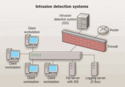
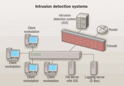
Chapter 5, which covers intrusion detection systems, states that all means of interconnecting wiring connections between a control unit, keypads, power supplies and accessories to the control unit must be monitored for the integrity of the interconnecting conductors or equivalent path. This is so that the occurrence of a single open or a single ground-fault condition in the installation conductors or other signaling channels and their restoration to normal is automatically indicated within 90 seconds. Wiring to all intrusion detection system initiating devices must be monitored for integrity so that the presence of an off-normal condition is automatically indicated to the user upon arming the system.
The standard states that when the system is armed, wiring to all initiating devices must be monitored for integrity, so that the occurrence of a single open, a single ground-fault condition or a wire-to-wire short is indicated by the control unit.
For exterior detection systems, the standard states that signals from exterior detection devices cannot be retransmitted to the AHJ unless physical verification of an intrusion is made. Physical verification must be made by either onsite verification or video verification.
The standard states that exterior structural detectors must include audio, contacts, optical fiber, protective cabling, proximity, shock sensors and stress sensors.
Exterior buried detectors must include electromagnetic, optical fiber, leaky coaxial and seismic types. Interior detection systems, when activated, must annunciate at the protected property and transmit an alarm signal.
Chapter 6: Electronic access control
Chapter 6 of NFPA 731, which covers electronic access control systems, mandates that when the portal is a door, readers must be mounted on the latch side. Clearance between the reader and the portal must be provided for the portal action appropriate for its application.
Access control systems must use electric locking systems to control the use of portals. Control of egress must comply with the requirements of the applicable codes and standards based on facility occupancy and usage. Locking systems must be installed in accordance with the manufacturer’s instructions. Portals must automatically close and lock when the portal is supervised by the access control system.
The chapter also states that a position sensor, required on all controlled portals, will monitor the position of the portal for held-open or forced-open conditions. It must be mounted so that no portion of the portal can be opened greater than 15.24 cm before activating the sensor.
Chapter 7: CCTV installation
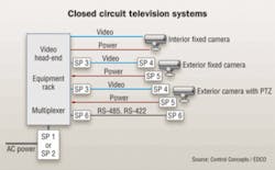
Chapter 7 covers the installation requirements for closed circuit television (CCTV) systems, and analog and digital imaging systems. This section says the application and use of these systems must be based on the requirements of AHJ, and the installer shall ensure that the final image meets the design requirements.
Camera selection and location must be based upon the requirements of the AHJ.
The standard states that the level of vandal resistance for these cameras must be determined by a risk assessment or the requirements of the AHJ. In the absence of a risk assessment or AHJ requirement, cameras must be installed so that the image cannot be impaired by vandalism. The cameras must be installed so that icing, sunlight angles, temperature extremes, wind loading and rain do not affect their operation.
The standard states that the camera field of view cannot have bright illumination behind the main subject. When the backlighting conditions cannot be met or the scenes have extreme contrast, high dynamic range or backlight compensation cameras must be used.
When enclosures are used, the correct size enclosure must be selected based on the dimensions of the camera/lens package and any other required equipment, such as connectors, other electronic devices or transformers.
Anchoring must be rated for the load and mounting surface. The standard says all anchoring sets must be installed per manufacturer’s instructions and be appropriate for the surface to which the anchoring sets are mounted. The system’s mounts must be rated for the weight, external weight (i.e., snow or rain), twist and wind loading of the equipment used.
Coaxial cable must have a jacket appropriate for the environment and be compliant with local codes. It must have a dielectric impedance of 75 watts, and the shield must be braided-100% copper material with an efficiency rating of 95% or better, or reverse foil over copper braid with 100% efficiency rating.
In installations where the coaxial cable flexes, such as pole-to-pole, a stranded center core must be used. In installations where the coaxial cable is fixed, such as inside a raceway, a solid center core must be used. The center core must be 100% copper with an outer diameter that matches the inner diameter of the center of the bayonet nut connector that is to be installed.
Chapter 8: Holdup, duress, ambush
In this section, NFPA 731 states that the means of interconnecting wiring connections between initiating, annunciating and remote control devices for these systems must be supervised so that the occurrence of a single open or single ground-fault condition in the installation wiring and their restoration to normal must be indicated within 200 seconds. Initiating devices must be located in such a manner to prevent unintentional operation by employees, janitors, cleaners, and others with access to the equipment.
The installation of holdup devices must meet the requirements of UL 681, Standard for Installation and Classification of Burglar and Holdup Alarm Systems. Fixed-in-place holdup alarm initiating devices must be mounted at a height that is accessible from their normal work position to the individuals responsible for utilizing the device.
For duress alarm systems, audible and visual signaling devices must be located at a point that is visible from the location of the duress alarm initiating device. The standard states that fixed-in-place duress alarm initiating devices must be installed within 1.2 meters of the workstation and accessible from their normal work position to the individuals responsible for utilizing the device. Portable duress alarm initiating devices must be in compliance with ANSI/SIA CP-01, Control Panel Standard-Features for False Alarm Reduction, Section 4.2.4.
The standard states that a duress alarm-initiating device must lock into the alarm position or display a visual indication when it is operated. Visual displays of a duress device’s operation must be permitted at the device, at the control unit to which it is connected, or at the location where the duress alarm signal is received. Visual indication of a duress device’s operation must require a manual operation to reset it.
For private duress alarm systems, each duress alarm-initiating device must be located so that it cannot be observed by the public. The activation of a duress alarm-initiating device cannot be obvious to a hostile party.
Likewise, for public duress alarm systems, each duress alarm-initiating device must be located so that it can be observed by the public. Each duress-initiating device must also be capable of being operated by the public.
The standard states that for ambush alarm systems, initiating devices must be located in or adjacent to the mechanism that is used to disarm the intrusion detection system.
The standard also states that the initiating of an ambush signal must be accomplished by entering a code sequence that is not similar to any code sequence that is used to perform any other operation in access control, intrusion detection, and holdup or duress systems.
Chapter 9: Inspection and testing
Chapter 9 covers the minimum requirements for the inspection, testing and maintenance of electronic premises security systems.
The chapter states that the owner or the responsible party must be responsible for the inspection, testing and maintenance of the system, as well as alterations to the system. Any system defects and malfunctions must be corrected, and the repair must begin within 24 hours of the indication that repair is required.
If a defect or malfunction is not corrected at the conclusion of system inspection, testing, or maintenance, written notice must be provided to the system owner or responsible party within 24 hours. The standard also states that a record must be maintained by the system owner or responsible party for a period of one year from the date the impairment is corrected.
(To obtain a copy of the full standard, visit www.nfpa.org)
BRIAN MILLIGAN is senior editor for Cabling Installation & Maintenance.


