Another look at zone cabling
Extending beyond the open office, zone cabling meets today’s and tomorrow’s needs.
When you think of zone cabling, the open office is what initially comes to mind. The zone cabling approach has been around for some time, specified and defined under TIA/EIA standards and well known for simplifying work area moves, adds, and changes (MACs). But even as zone cabling brings flexibility to the open office, it’s a topology that is extending its reach to other areas and holds many benefits for the deployment of advanced and future technologies.
Just as our industry continues to evolve, so does zone cabling. The time has come to give it another look.It’s not just for open offices anymore.
Traditional structured cabling involves multiple horizontal copper runs all the way from the telecommunications room (TR) to each work area. For very small offices, this approach works fine. But in many office environments, traditional structured cabling can mean hundreds of lengthy copper cables that are difficult to manage, virtually impossible to change, and extremely arduous to remove when complying with building codes that require removal of abandoned cable.
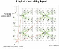
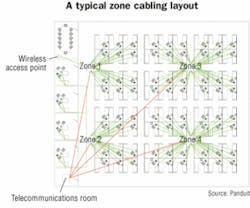
Alternatively, a zone cabling approach involves a logically placed connection point in the horizontal cable so that copper or fiber runs are routed from the TR to zone boxes and to specific work areas or zones. Shorter copper runs then extend from the zone box to each work area in that zone.
A properly executed zone cabling plan has many immediate and long-term benefits. It results in a more manageable, accessible, and flexible cabling topology, which has a direct impact on material costs, labor, and future MACs and maintenance. For these reasons, zone cabling has become an important aspect of revised TIA/EIA standards, which specify and define zone cabling under TIA/EIA-568-B.1 Commercial Building Telecommunications Cabling Standard, TIA/EIA-569-B Commercial Building Standard for Telecommunications Pathways and Spaces, and TIA/EIA-942 Telecommunications Infrastructure Standard for Data Centers.
A specific example of TIA/EIA support for zone cabling occurs in Work Area Section 6.1 of 568-B.1: “Work area cabling is critical to a well managed distribution system; however it is generally non-permanent and easy to change.”
Non-permanent and easy to change is the essence of zone cabling.
When compared to traditional “home run” cabling. a zone cabling approach makes it quicker and easier to manage MACs because shorter cable runs are used to connect zone boxes to local work areas. Zone cabling enclosures are easily accessible for MACs and maintenance; and, because of the localized topology, these changes only affect one small zone at a time. This structure eliminates widespread downtime and network disruption, thereby maintaining maximum productivity.
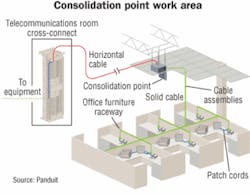
Zone cabling can be achieved with a consolidation point (CP), a multi-user telecommunications outlet assembly (MUTOA), or a telecommunications enclosure (TE), each of which has its own advantages and requirements under TIA/EIA standards. Zone cabling products come in a wide range of shapes and sizes to accommodate various applications and mounting options.
Points of interest
As defined under TIA/EIA-568-B.1, a CP is a passive interconnection point in the horizontal cabling located at least 15 meters from the TR. The horizontal cabling entering the CP (cross-connections are not allowed) is either terminated to a jack, patch panel, or punchdown block. The CP is limited to serving a maximum of 12 work areas and must be located in an accessible permanent location tied to the building structure. CP enclosures can be located in discreet, unobtrusive locations, such as plenum ceiling and underfloor spaces, or mounted to a wall. Some enclosures, such as the PanZone Wall Mount Consolidation Point Enclosure, can be mounted recessed in the wall for a discreet, streamlined look.
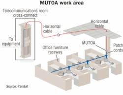
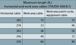
MUTOAs differ from CPs in that they technically are work area outlets, meaning that the horizontal cable is routed directly from the TR to the MUTOA in a jack-to-jack configuration and remains intact when the open office environment is changed. Work area patch cords, sometimes routed through office-furniture pathways, connect network devices directly to the MUTOA. Table 6-1 in the TIA/EIA-568-B.1 standard determined the maximum copper cabling lengths for the work area cable. MUTOAs must be labeled with the allowed maximum-length work area cable to avoid confusion when work area cables are added.
Like a CP, a MUTOA is also limited to serving 12 work areas and must be located in an accessible permanent location; however, MUTOAs are not allowed in plenum spaces, including in-ceiling or underfloor locations. A MUTOA is ideal for a cubicle cluster, as well as a computer lab where it can be located on a wall to serve a row of computers. Adding workstations is quickly achieved with a MUTOA because only patch cords need to be added to connect to the network. While the MUTOA offers the benefit of a lower-cost zone cabling solution, some prefer the CP because of its flexibility to mount in the ceiling or floor.
A tiny treasure
With the update to the TIA/EIA-568-B.1 and 569-B, zone-cabling topology expanded its reach by permitting active equipment to move outside a TR into a TE. In addition, a TE can now be used to implement a centralized optical-fiber cabling architecture, often called a “collapsed backbone.” The benefit is a TE using optical fiber can now extend up to 300 meters from the main cross-connect, and no longer is restricted by the 90-meter copper limitation. Since optical fiber also has higher potential bandwidth than copper, fewer cables are needed because optical fiber can replace multiple copper cables.
Because the standards define the TE as a tiny TR, an architect can now design new construction with fewer TRs, which results in more usable space for building owners. TEs are ideal for situations in which an existing TR cannot cover an entire floor of a building and maintain the maximum horizontal cable distance of 90 meters. For example, a school could use a TE to connect classrooms that are beyond 90 meters from its TR.
Out of office
Now that we have reviewed the fundamentals of zone cabling and understand its benefits, let’s look at how this topology is extending its reach to other areas of the cabling infrastructure, from data centers to wireless building automation systems.
In the data center, the zone distribution area (ZDA) as defined by TIA/EIA-942,is an optional interconnection point in the horizontal cabling infrastructure. The ZDA acts like a CP in the data center, providing a convenient termination point for areas that require frequent reconfigurations and flexibility. The ZDA supports a maximum of 288 connections.
The ZDA is often located within the raised floor of the data center, freeing up valuable space in the cabinet where density is of the utmost concern. Precabling to ZDAs in the data center also allows the rapid deployment of server cabinets, which is useful for preconfigured cabinets used in grid computing, as well as for areas designated for staging, setup, or testing new cabinet configurations.
For mainframe or other freestanding equipment applications, a ZDA can also save valuable floor space by locating a termination point in an underfloor enclosure rather than in an adjacent cabinet. As an added benefit, a ZDA also provides flexibility because the equipment can be placed anywhere there is a zone box. ZDA enclosures, such as Panduit’s PanZone In-floor Zone Cabling Boxes, provide up to 11 rack units of space and fit into standard 24 x 24-inch raised floor panels.
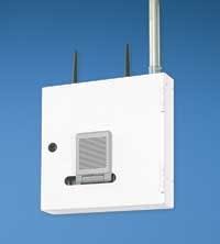
As more enterprises use wireless technology, zone cabling can ease its integration into the network. With a zone-cabling topology in place, wireless access points (WAPs) can be added quickly by connecting to local zone boxes that position them in logical locations to provide the best coverage. The greater the number of zones, the more flexibility you have in deploying a wireless network.
Because wireless is often required in more remote areas or unusual environments, it can also be difficult to remain within 90 meters of the TR. As discussed previously, TEs can extend backbone cabling closer to a WAP for easier deployment in remote areas.
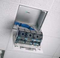
Ratification of the 802.3af Power over Ethernet (PoE) standard by the Institute of Electrical and Electronics Engineers (IEEE) has provided the means to power several types of devices over the network, including WAPs and surveillance cameras. A PoE switch, powered patch panel, or other power-injecting device can be located in a TE and used to power these devices. For example, consider the setup in which a powered Panduit DPoE patch panel is located inside a PanZone Active In-ceiling Box. A single copper cable could feed both a network connection and power to a camera or WAP. The use of zone cabling in conjunction with PoE devices eliminates the expense of running separate power or having to connect all the way back to a TR.
On the horizon
The advantages of zone cabling are not limited to the open office, or even at the data center, wireless network, and PoE infrastructure deployments. As we look to the future, many emerging technologies will extend zone cabling’s reach.
The TIA formed the TR-42.9 Industrial Telecommunications Infrastructure subcommittee to develop standards for industrial buildings and facilities beyond the scope of current commercial building standards. As Ethernet becomes more prevalent in industrial environments, zone cabling is an ideal method for delivering network connections out to the factory floor. Zone cabling in this environment enables strategic division of the various industrial functions and easy repositioning of connected machinery without having to reconfigure lengthy runs back to a TR. Where TR space on the industrial floor is impractical, an IP (Ingress Protection)-rated TE located on a wall would be an ideal alternative.
Building automation systems (BAS) include security, life-safety, heating/ventilation/air conditioning (HVAC), and energy-management systems. The TIA/EIA-862 Building Automation Systems Cabling Standard for Commercial Buildings specifies a horizontal connection point (HCP) for BAS to help in the planning and installation of a building. Using a zone-cabling topology, BAS devices can be strategically connected to the zone (HCP) for better maintenance and logical placement. When new BAS devices are added to an area, only a short cable run is needed to connect to the network, saving on material and installation costs.
As emerging and future technologies develop, the wide range of available zone cabling products will continue to enable dynamic environments where MACs, upgrades, and the addition of new technologies are simplified, resulting in reduced total cost of ownership. Whether it’s wall-mounted, in the floor, or in the ceiling, and whether it’s active or passive, zone cabling deserves another look.
BRETT A. SWETT is business development manager for Panduit Zone Cabling and Wireless Solutions (www.panduit.com).
