Two cable testing standards loom on the horizon
Mark Johnston
Microtest, Inc.
Installers and users of high-speed unshielded twisted-pair cabling systems will soon be faced with two standards for testing. IS-11801, the new international standard from the International Standards Organization, covers many physical media, including UTP, shielded twisted-pair cable and optical fiber. In North America, a similar document is Electronic Industries Association/Telecommunications Industry Association-568A, approved in September 1994.
The goal of the American National Standards Institute is that United States standards, such as those published by the EIA and TIA, be consistent with international documents produced by the ISO. However, although IS-11801 covers some aspects of testing, neither the U.S. nor the international document includes detailed information on how to certify installed cabling. A separate EIA/TIA task group has been working on this issue. PN-3287 is the working title of the draft document that focuses on field testing of UTP cabling. PN-3287 is scheduled to be published by June 1995.
IS-11801 and TIA-568A/PN-3287 are similar in many ways; however, in several significant ways that affect testing, they are quite different. A good place to start in examining and interpreting these differences is to understand what people mean when they say the cabling has been tested.
For example, an end user may be told by the installer that the cabling has been tested and it is OK. The end user may think that the installer actually means that all the cabling has been tested and is up to specification. The phrase uttered by the installer, however, may really mean that "the subsegment of the link that was tested is OK. Whether your final end-to-end link will ever pass high-speed data is anyone`s guess."
Installers, then, typically test only part of the final channel. An end user must understand this and know what is being tested. Otherwise, incorrect assumptions about the capability of the link can easily be made.
To better understand this confusing point, let us compare the link models of the TIA and the ISO. The typical links needed to transmit information between a hub and a personal computer, as defined by TIA-568A and IS-11801 respectively, are similar, but not identical. In the TIA-568A model, an installer usually works with a basic link, while an end user requires a channel to connect an office workstation to a hub in the telecommunications closet. In the IS-11801 model, an installer usually works with a link. Performance characteristics for a channel are not defined in this model.
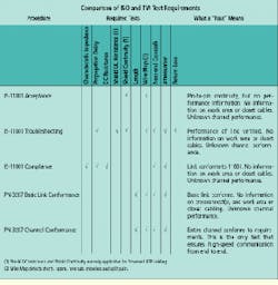
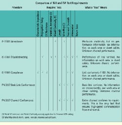
A "pass" indication on a tester can mean different things, then, depending upon what tests are made and which model is being applied by the installer. The IS-11801 standard includes three test suites--one each for acceptance, troubleshooting and compliance. The PN-3287 document includes two test suites--one for basic link conformance and one for channel conformance. Of the five different test suites, only the PN-3287 channel conformance tests actually give any guarantee that your high-speed applications will run on the cabling.
Channel conformance is what most end users are really looking for when they ask for cable test results. Unfortunately, PN-3287 basic link tests and all IS-11801 tests do not verify channel conformance because they do not test all the components of the channel.
Other testing issues
Measurement accuracy is a key concern that is not addressed by IS-11801, but is discussed in detail by PN-3287. What does it mean when your crosstalk measurement fails by 0.1 decibel, when your test device has plus-or-minus 2-dB accuracy? It really means your measurement result is uncertain. PN-3287 requires compliant test equipment to flag all results that fall into this zone and provide suggestions for further actions to resolve the uncertainty.
What if a crosstalk measurement from your handheld tester disagrees with a network analyzer`s results? These different devices may give different results, yet they are both correct. How can this be? Basically, it is because of the different test connections used; you are measuring in different testing environments, so your results are likely to vary. Unless the test setups are identical, it is difficult to correlate results. In fact, even with the same setup, it is unreasonable to expect two network analyzers testing cabling to agree to better than 1 dB. Annex A of PN-3287 describes how such measurements should be made.
Measurement accuracy is also affected by where you measure in the channel. PN-3287 recognizes the need to test both a basic link and a channel. The channel is typically terminated at each end by the ISO-8877 modular 8-pin connector. The mated connection at each end of the channel is not included in the channel definition; instead, it is considered part of the equipment at each end. The test equipment, then, must attach to this connector and yet measure the crosstalk past it. The residual crosstalk of the mated connection must not be included in the measurement.
Although it is possible to cancel the effect of the mated connection for any known, unique jack-plug combination, uncertainties in the manufacturing and terminating processes create unpredictable crosstalk characteristics for the connector, which is why the near-end crosstalk requirement for this connector is only 40 dB at 100 megahertz. This means that measuring equipment, including network analyzers, used to test through an unknown modular 8-pin connection will have more uncertainty and more inaccuracy than a tester using a connector with more stable and predictable characteristics. In recognition of this, draft 8 of PN-3287 permits two accuracy levels for test equipment.
So when you are looking at cable test results, be sure you know what you are getting. The point of cable testing is to ensure the cable plant meets the requirements of your intended application. Whenever possible, test the entire channel.
IS-11801 and PN-3287 call for three and two test suites, respectively. Of the five test suites, only the last, PN-3287 channel conformance testing, actually tests end-to-end channel conformance.
Mark Johnston is director for technology development at Microtest Inc., Phoenix. He is a voting member of EIA/TIA TR41.8.1, has contributed to IS-11801 and is on the technical advisory board of the Certified Network Expert consortium.

