Preparing modular patch cords for field-termination
Robert Y. Faber, Jr., RCDD, and Valerie Smith, EE, The Siemon Co.
Problem
One of the most difficult telecommunications products to field-terminate is the modular patch cord. It requires practice, patience and manual dexterity to assemble a patch cord without disturbing the cable lay; if the disturbance is too great, the link will fail a near-end crosstalk test. A properly terminated patch cord, however, will pass a continuity test and satisfy the transmission requirements of a particular category rating?Category 3, 4 or 5 as defined by Telecommunications Industry Association/Electronic Industries Association-568A.
Solution
Although it does not guarantee success, the following termination procedure can improve consistency and overall performance of field-terminated modular patch cords.
Procedure
1) Cut a length of cable of the proper category, with enough extra to permit termination at each end. Strip back approximately 1.5 inches of cable jacket at one end and be careful not to nick, twist, damage or otherwise disturb the conductors.
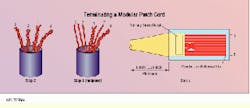
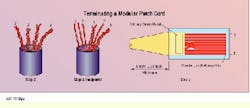
2) Familiarity with the T568A and T568B wiring schemes will help you orient the stripped cable and arrange the conductors. For example, if your cord is to be wired to the T568A scheme, rotate the stripped cord until pair 3 (green) is on the left. Fan out the pairs in this order, from left to right: pair 3, pair 2, pair 1, pair 4 (green, orange, blue, brown). The pairs should remain twisted at this point.
3) Hold the pairs in position by squeezing the base of the cable jacket between thumb and forefinger. Untwist pair 3 first. Untwist pair 2 to the jacket base, and spread the tip and ring conductors in a OVO shape around pair 1. Remove the twists from pair 1 and orient it between the conductors of pair 2. Position the conductors of pair 4 last. Do not untwist the conductor pairs past the jacket base.
4) With practice, you will see cable has certain segments where all pairs are properly oriented and need only to be guided into position. If you notice the pairs are not falling into place during assembly, trim off another 0.5 inch of cable and repeat the process.
5) Still holding the jacket base with the pairs in position with your left hand, grasp the conductors with your right hand and rotate them half a turn clockwise and half a turn counterclockwise. This flattens and straightens the conductors, making it easier to insert them into the plug.
6) Trim the conductors. The length to which you trim depends on the plug being used, but trimming back to 0.5 inch beyond the jacket base is usually sufficient. For Category 5 terminations, the length of the untwisted pairs must not exceed 0.5 inch. Trim carefully; removing too much will keep the conductors from seating properly, and you will have to start over.
7) Insert the plug over the spread-out conductors, pushing the cable jacket past the primary strain relief. Inspect the front of the plug to ensure all eight conductors have bottomed out.
8) Crimp the plug with a crimping tool.
At the end of step 2, the twisted pairs should be arranged 3, 2, 1, 4 for the T568A wiring scheme. At the midpoint of step 3, pair 3 is untwisted and pair 2 is "veed" over pair 1. At the end of step 7, the conductors have been inserted into the plug.
Robert Y. Faber, Jr., RCDD, is a corporate trainer, and Valerie Smith is an electrical engineer at The Siemon Co., Watertown, CT.

