Emerging stakeholders create new considerations for structured cabling design
By Jeff Drenovsky, Environmental Systems Design Inc.
Traditionally information and communications technology (ICT) systems engineers have designed structured cabling and technology systems with only one of their client’s departments in mind-the information technology (IT) group. Now, with lighting, mechanical systems, cellular enhancement and audio visual equipment coming to rely upon the structured cabling system for connectivity, another department-facilities management-has emerged as an important stakeholder in this aspect of building construction.
Similarly, as buildings have become more and more intelligent, it’s not just phones and computers that have a technical-wiring component, but security and maintenance measures have become technology-driven too. For example, many companies have building automated systems (BAS) for heating, cooling and/or ventilation, or feature intelligent lighting control. Facilities management, not IT, maintain and manage these systems.
With multiple voices at the table, designers are challenged to fully understand each party’s needs and develop a unified structured cabling design solution that meets the demands of multiple clients within the client.
Three ways to separate cabling infrastructure
In order to succeed at this lofty goal of meeting the total, combined and separate objectives of the IT, facilities group and more, the first step is to understand the three concepts of systems separation that govern cabling and wiring: physical, visual, and pathway separation.
Physical separation - Corporate security policies for change control management may require moving facilities-managed systems to separate rooms from the networking equipment. This allows easier access by technicians or electricians when maintaining facilities-related equipment. Within the IT-managed spaces, there may be additional concerns. Many businesses today have governmental and/or corporate policies and regulations that require a physical separation of their cabling and networking infrastructure. For example, private firms working for security-sensitive government agencies may have to create a physical separation of cable terminations and network equipment that house sensitive information from their operational network. Businesses that process financial transactions often require the computing devices running or storing those financial transactions to be separated from the company’s general computer equipment in order to conform with internal PCI compliance audits. HIPAA compliance requirements also demand very specific levels of data security related to patient health information, which may drive care organizations to consider separating physical infrastructure to prevent unauthorized access.
Cabling designers will need to sit down with each of the corporate stakeholders to determine the level of physical separation required. The ultimate design could include two totally separate adjacent rooms in which the cabling infrastructure is completely divided based on function. Or, the company may require two separately caged areas within a single room. If a client chooses to co-mingle the equipment, the ICT design engineer must be aware of products that can increase security at the rack level, including locking covers for patch panels/switches, port-blocking devices, special card access for server cabinets, etc. At the work area, design elements such as security plugs, locking covers or the use of keyed jacks can be used to prohibit unauthorized connections to secured networks.
Visual separation - Whether a physical separation is required or not, a visual separation may be necessary as well. Using the same type, but different color wires can create a visual separation of systems within a shared pathway or space. Visual identification of the systems in a congested ceiling environment or within a crowded telecommunications room may be important to designate cable function and can be helpful in determining which wires service which systems. For example, blue cables and jacks may represent normal network connections and orange or yellow cable and jacks may be used for security devices, violet cable and jacks may represent audio visual infrastructure, etc. A hospital may have separate vendors for network infrastructure, nurse call systems, security, audio visual systems, low voltage lighting, mechanical systems, etc., all working in the same dark ceiling spaces. Having a visual separation plan for maintenance allows individual contractors working on cabling infrastructure to easily identify one from the other as to prevent inadvertent damage to any system.
Pathway separation - For businesses that service different clients, industries and/or types of businesses subject to varying regulations, separating the cable pathways may be necessary. For example, one business with a government client is required to separate the cabling that houses classified government information from the cabling that houses the company’s day-to-day operations by 18 inches when installed. This separation has to be maintained for the length of the entire cable route-from point A to point Z. This can be a challenge depending on the physical layout of the building, but when disclosed during the pre-design phase, it’s possible to segregate cabling routes, wherever they are housed.
Less severe pathway separation may be achieved with options such as separate conduits for different systems, pathway dividers within a shared basket tray, or with the use of colored J-hook supports. The ICT design engineer must marry the proper separation solution to the requirements of the multiple stakeholders.
Best practices for optimizing cable installation
In addition to the separation of cabling according to building function and program requirements, there are a few best practices that can be applied to most cabling installations, regardless of industry or separation type. These include the following.
Institute internal corporate processes. During the cabling pre-design phase, it’s important to create internal corporate processes that determine room/building area program function and personnel authorization. This will include which employees or vendors are allowed to access areas/rooms on a day-to-day basis and for prescheduled maintenance. Maintenance, especially where equipment downtime applies, should be scheduled as early as two to six weeks in advance, in order to ensure the seamless rerouting of equipment function, when necessary, and to alert staff of potential downtime.
Establish a change control process. Even when organizations have instituted internal processes and lead time for maintenance, there’s still the possibility of an inadvertent shutdown. Establishing a change control process can help reduce the amount of risk for each space, equipment and cabling route. This includes documenting risk management and notifying teams managing the systems.
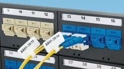
Use signage to differentiate. Another way to create a distinction between cabling system functions is to use signage. Sounds obvious, but many organizations don’t take advantage of this simple way to differentiate. A sign for each room could specify what’s inside, or signage within a room might designate various equipment cabinets. It can also offer required separation and more.
Developing and installing a comprehensive structured cabling system for diverse applications-one that will meet the needs of the facilities management group and the IT team while meeting compliance requirements-requires utmost collaboration between the ICT systems design engineers and all departments on the ground. From the pre-design phase to installation, ICT systems engineers and contractors must fully understand the needs of each of the organization’s teams. When this happens, the project can achieve structured cabling design success.
Jeff Drenovsky is a senior associate with Environmental Systems Design, Inc. (www.esdglobal.com).
Case in point: Top 10 banking firm
One large, international banking firm has a number of different internal departments, each with their own cabling requirements-facilities management, network management or IT, audio-visual and a physical security team. Typically, each department would hire their own contractors to work on department-specific projects, but this could mean as many as four different contractors working in the same space, which also houses secure client information. The banking firm was concerned that a lighting contractor, for example, could access servers with personal data or accidentally disconnect critical cabling.
Working with Environmental Systems Design Inc., the banking firm agreed to separate the cabling into two rooms: Room A for secure client banking data and Room B for the bank’s day-to-day operations cabling. Room A is officially called the telecommunications room, or TR, and has all the network management necessary to house their clients’ banking and data server equipment. Room B is the facilities technology room, or FTR, with security panels for access control, network wiring for security cameras, sound masking systems, equipment for AV and cable TV and electrical distribution equipment, including the UPS system.
Because Room B houses the cabling for most of the bank’s internal departments, ESD used various color schemes to differentiate between the systems. Now, when someone enters Room B, a quick look determines which cabling belongs to which department.
Ultimately, the physical and visual separation of systems has helped all departments and their contractors identify the right cabling, while containing and minimizing the risk to personal client data.
-J.D.

