By Russell Kirkland and Luis Abreu, Corning Optical Communications
If you’ve invested tens of millions of dollars building a reliable, robust, and high-performance network system, you need to now ask yourself some serious questions: What will you do in order to ensure higher performance, improved reliability, and better utilization of your network? Will you be proactive, or will you react when your system starts to lag and switch overutilization begins crashing critical applications? Is gambling with your system worth the cost to you, your customers, and your reputation?
The answer to all these questions is network monitoring. Many people immediately think of security applications when they hear the term “network monitoring.” However, while network monitoring does include the ability to analyze potential security threats like denial-of-service attacks and hackers, it also can be used by network administrators to monitor real-time performance of their network and identify bottlenecks or other potential performance issues. Monitoring done correctly should allow you to see error, performance, and utilization data, and ensure the accuracy of changes, validating that they only produce desired results. This means that you can set a baseline of application performance before migrating or consolidating data center components, monitor performance throughout the move, and then optimize the new system for maximum utilization, availability, and performance. Currently some of the world’s leading financial institutions, large commercial storage area networks (SANs), and most innovative consumer companies utilize the benefits of this preventive approach to realize a return on their investments in months rather than years.
SPAN and tap
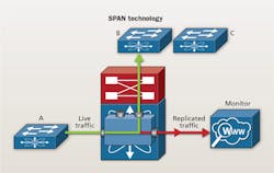
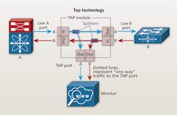
There are two technologies currently being used in network monitoring systems - SPAN (switched port analyzer), also known as port mirroring, and tap (traffic access point). A SPAN port copies traffic from any traffic port to a single unused port. SPAN ports also prohibit bidirectional traffic on that port to protect against backflow of traffic into the network. The SPAN port then directs packets from its switch or router to the test device for analysis. A tap is a passive component that allows non-intrusive access to data flowing across the network and enables monitoring of network links. A tap uses passive optical splitting to transmit inline traffic to an attached monitoring device without data stream interference.
In order to decide which technology is right for your network, let’s take a moment to compare these two solutions. Some people refer to spanning as a passive technology, but a SPAN port is not truly passive because it has a measurable effect on network traffic. Spanning changes the timing of the frame interaction and will drop frames if the speed of the SPAN port becomes overloaded. The spanning algorithm being used by the device is not its primary focus; switching or routing is the primary focus, therefore spanning will be suspended if replicating a frame becomes an issue. The switch will always treat the SPAN data with a lower priority than normal traffic. Additionally, SPAN ports drop all packets that are corrupt or below the minimum size, and they do this without notifying the user. The switch may also drop Layer 1 and some Layer 2 errors based on priority level. This means that your network monitoring device may not receive all the data required to conduct an accurate analysis of system performance. A SPAN port cannot fully replicate any duplex link.
As bandwidth requirements increase to 1G and beyond, you need to look at a different technology that will allow you to see all network traffic, including errors and regardless of packet size, in real time. A tap enables you to do exactly that. Taps are truly passive. They provide visibility into every packet of data without adding any additional load onto the network. Taps use optical splitters to transform your “one-in-one-out” patch panel connection to a “one-in-two-out” connection. Because the device is simply splitting the signal instead of replicating it, you can take a portion of the signal offline, or out of band, to do analysis of the I/O traffic without affecting live applications. Because this is live traffic, you are guaranteed to receive all traffic in the link in real time regardless of the data rate.
It is important to note that a SPAN port must be configured by a network engineer, taking them away from more critical tasks. Additionally, if the SPAN port is not disabled during a network refresh, it is possible for that port to be cabled to serve as a network port, creating a “bridging loop,” which will result in network performance issues. Because a tap is truly passive, it does not need to be configured and does not require any of the valuable processing capabilities of your switches or programming time of your network engineers.
Technologies and applications
When we compare prospective network monitoring technologies, cost is also something we must consider. Other than the additional expense of using a network engineer to configure a SPAN port, the cost of monitoring a SPAN port increases with higher data rates. This is due to the fact that a 10G switch port is more expensive than a 1G switch port - whereas a tap port at 1G costs the same as a tap port at 10G or even 40G. For this reason, optical tapping is becoming a more popular solution for higher data rates.
Spanning can be successfully used as an access technology for low-bandwidth, application-layer events like conversation analysis, application flows, and VoIP reports, but it is not a good solution for traffic security compliance monitoring or lawful intercept due to a lack of absolute fidelity. If you are running a high-data-rate system and want to ensure optimum infrastructure performance while conducting traffic security compliance monitoring or lawful intercept, you must monitor at the physical level, conduct analysis at the protocol level, and collect all traffic in real time. Taps allow you to do that.
Even though tapping is a better solution for most of today’s networks, not all taps are created equal. A tap can be either integrated or non-integrated into your structured cabling and can use either fused biconical taper (FBT) splitters or thin-film splitters. Taps also can be presented with different connector types, some more useful than others.
Integrated taps perform the same function as your normal structured cabling network, but also send a portion of the light to the monitoring electronics. Conversely, non-integrated taps are deployed as standalone devices outside your structured cabling network. With traditional non-integrated taps, whenever you need to change monitored ports, the link has to be temporarily disabled to make new connections between monitored ports and passive tap devices. An integrated tap module allows you to perform moves, adds, and changes to monitored ports without disrupting the live network, annually saving you up to eight hours in downtime.
Another major difference between integrated vs. non-integrated taps is the exposed ports. Non-integrated taps have ports for both network and monitoring connections exposed, while integrated taps only expose the network ports. For integrated taps, the monitoring ports are connected on the backplane of the system, which simplifies the cabling infrastructure, enhances operational efficiency and, because there are no accessible monitoring ports, provides for a more-secure environment.
By incorporating the functions of a tap within a standard module, an integrated tap module enables you to save valuable rack space that can be used for revenue-generating equipment. With an integrated tap module, you can cable and tap up to 72 ports per rack unit (1RU) - maintaining the same density as a non-tapped link. With a non-integrated tap solution, in addition to the rack space required for the cabling itself, extra rack units would be required to tap the 72 cabled ports.
Performance considerations
Performance is a key consideration in data center networks. Integrating the tap into your structured cabling solution eliminates two connections from the live link, as compared to a non-integrated solution. This, along with the use of high-performance thin-film multimode splitter technology, provides reduced link attenuation, which translates into extended Ethernet and Fibre Channel distances.
Loss is not the only thing that can affect Ethernet and Fibre Channel distances. Some tap modules in the market today still use FBT splitters, which can caused increased bit error rates (BER) based on where they are placed in the system due to the transmission penalties they introduce. Thin-film splitters do not introduce any BER penalties, so you have the flexibility to install them anywhere in your system without worrying about BER effects.
Finally, integrated tap modules allow you to incorporate tapping into all your links on day one, with the option to only monitor the links you need. As your network monitoring requirements grow or change, simply add the required cabling between the tap modules you’ve already installed and your network monitoring equipment. Because there is no need to change your cabling infrastructure, there will be no disruption of the network. Additionally, because integrated tap modules occupy the same space as traditional MTP/LC modules, adding monitoring to an existing network is as simple as swapping out a tradition module for a tap module.
Taps can be presented in multiple connector types, but having a tap port presented as an MTP connector in the rear of the module provides you with maximum flexibility when designing a structured cabling network. The MTP connector footprint allows separation of live production network ports and tap ports into different cabinet locations if desired. Using this capability to centralize the active monitoring equipment, rather than installing across multiple cabinet locations throughout the data center, provides cost savings by optimizing the use of active monitoring equipment and reducing the risk of patching errors.
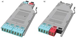
Examples of a fully integrated, fully passive optical tap solution that uses high-performance thin-film splitters are the EDGE and EDGE8 data center solutions pictured in this article. Both solutions include a full suite of structured cabling components to support a tapped network. The Base-12 solution uses a 12-fiber MTP connector for connectivity, with trunks, modules and harnesses in 12-fiber-count increments. The Base-8 solution uses 8-fiber MTP connectivity with trunks, modules and harnesses offered in 8-fiber-count increments. A Base-8 solution provides an optimized transition to higher data rates, since future transceivers are projected to use either 2-fiber duplex or 8-fiber parallel optics.
Why would you invest your capital and stake your reputation on a system in which you can’t see what is going on and can’t guarantee application performance? Don’t wait until you are in the middle of a major data center outage to start thinking about network monitoring. Do your homework and implement a plan now.
Russell Kirkland is a system engineer II, enterprise networks and Luis Abreu is a product line specialist for Corning Optical Communications.


