For over a decade, Power over Ethernet (PoE) and PoE+ have provided organizations with a simple and convenient option for powering devices such as IP phones and low-power cameras. Now, as technology continues to evolve, the structured cabling infrastructure is being used to support an increasingly diverse and power-hungry set of devices whose appetites exceed the current capabilities specified by today’s PoE+ standard. It is clear that the developing PoE ecosystem will continue to grow through new applications. The challenge to future network infrastructures, especially cabling, is this: How can IP traffic be isolated and protected from the additional heat and noise that will be generated from more than three times the power that is currently available?
The Evolution of PoE
Power over Ethernet (PoE) was first adopted in 2003 with the original 802.3af standard, providing up to 15W of DC power with 12.95W minimum available to the powered device. The ability to power IP devices, primarily VoIP phones at that time, proved to be very cost effective for customers. As years went by and advanced VoIP phones began to require more power, the IEEE ratified 802.3at in 2009, allowing up to 30W of DC power with 25.5W of power available to the powered device. This accommodated VoIP phones with larger full-color displays, as well as some of the early IP security cameras and other IP devices.
PoE remains very cost-effective, and therefore a very popular technology. As such, the need for more power continues to grow, and the IEEE has begun work on a new standard – 802.3bt. The technology being developed for 802.3bt will likely introduce the following advancements over previous generations of PoE:
- Deliver power over all four pairs instead of only two
- Deliver power with 10Gbps throughput, not limited to 1Gbps
- Deliver power in two increments (depending on what is needed) – 60W / 100
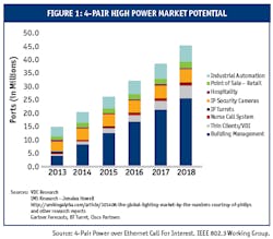
Figure 1 below shows the forecasted growth of next generation PoE technology, and examples of devices that will require more than the currently available 30W of power. The markets with identified needs span today’s infrastructures and include areas such as healthcare, retail, building management, IP turrets, thin clients, video conferencing, IP security cameras, and industrial networks. Significant grown is expected in building management opportunities, as well as industrial automation and thin clients.
Understanding the Power-Heat Relationship
While the IEEE standard is in development, several manufacturers and technical consortiums are working to establish the boundaries of technical feasibility. It has been demonstrated in a lab environment that it is possible to supply at least 60 watts over a 100-meter 10GBASE-T link. However, increasing power delivery increases current flow, resulting in an increase in heat generation within the cabling infrastructure. It is expected that this increased power delivery will significantly impact cable bundle temperatures, and the de-rating factors originally recommended in 2009 in the TIA TSB-184: Guidelines for Supporting Power Delivery Over Balanced Twisted-Pair Cabling will need to be revised. As a result, the standards bodies of TIA, ISO and CENELEC are investigating the impact of delivering an average of 1 amp per pair within the cable and revising their recommendations.
In general, cable temperature rise with PoE deployment is a function of several factors:
- Gauge Size: Larger copper conductor reduces the resistance and allows for easier current flow, generating less heat.
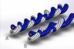
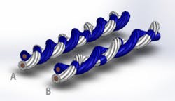
- Twist Rate per Inch: Higher categories of cable generally have increased pair twist rates. This increased twist rate creates a longer electrical path per given cable length, as depicted by Pair A in Figure 2. This results in increased resistance to current flow and increased heat generation.
- Current: As current increases, so does heat generation.
- Thermal Insulation/Diffusion: This refers to the ability to shed or disperse the generated heat to the outside environment. Cables unable to cool will increase in temperature until equilibrium is reached.
- PoE Deployment Density: Heat generation increases as the number of PoE drops increase within a pathway.
Figure 2: Increasing twists (Pair A vs. Pair B) increase DCR
The Impact of Higher Power on Cabling
There are three major reasons for an interest in heat: environmental heat loading to the facility, safety, and the impact to electrical performance.
Environmental heat loading
This can be a fairly straightforward calculation as it is based upon the number and length of the drops in conjunction with the cable unit resistance and electrical current traversing the pairs. Deploying large amounts of high power PoE may increase the HVAC requirements for a facility and raise the average ambient and peak temperatures experienced by the cabling.
Safety
Excessive temperatures from heating may lead to melting insulation and the immediate failure of infrastructure components. However, elevated temperatures also age components at a faster rate, and the jackets and insulations may become brittle when exposed to elevated temperatures for extended periods. This may result in cracking or segments of insulation falling off the cable. Flame retardant properties may also be reduced as vital components within the compounds degrade or evaporate. Cables have temperature ratings, such as 60 or 75°C, which are designed to ensure their operation over their lifetime. However, failing to account for thermal gain from PoE deployments may drive a cable above its safety listing when installed in a hot environment. Given the increased current load and the increased heat generation that comes along with it, those specifying cabling infrastructures should consider cabling with rating of at least 75°C, particularly for those areas with an already elevated ambient operating temperature.
Electrical Performance
Heat increases the losses within the cable and reduces the effective reach of copper cabling, making a 100-meter reach with minimally compliant cable unobtainable. Therefore ambient conditions as well as thermal gains must be considered when calculating length reductions for system operations.
Testing that Replicates the Real World
The complexities of real world installations create an infinite number of possible test scenarios. Today’s LAN cables are subjected to a wide range of installation conditions, such as extremely large bundles, covered trays and conduits. Care must be taken not to underestimate the impact of cable heating due to increased power delivery. However, the converse is that the overestimation of temperature rise can lead to the creation of onerous installation or manufacturing requirements, which could limit the potential of the technology and severely curtail its deployment.
Cable tested in an environment that resembles a vacuum flask with little outward heat convection shows alarmingly high heat gains, but this scenario does not reflect the installations of today’s infrastructure. To accurately determine the effect of heat on a cable’s performance, testing scenarios must replicate real-world installation environments as closely as possible. To this end, the TEK Center at Berk-Tek has both modeled and tested the temperature profiles of numerous sizes of cable bundles in preparation and support of the standardization efforts for the next generation of PoE.
The TEK Center recently published a Test Report entitled Next Generation Power over Ethernet and Temperature Testing. This report examines temperature rise when power is applied to different types of cable in open and closed trays, in addition to cable inside conduit. The TEK Center evaluated the performance of various types of construction from several different manufacturers, and included Category 5e through Category 6a. To avoid confusion, this paper will focus on one representative product from each category tested:
- Category 5e: LANmark-350TM
- Category 6: LANmarkTM-1000
- Category 6A (unshielded): LANmarkTM-10G2
- Category 6A (foil-isolated): LANmarkTM-XTP
The testing focused on two bundle sizes of 37 and 259 cables. The quantity 37 was selected to match testing being done by the industry standards bodies, and because of its approximate size to cable bundles servicing 24 and 48 port panels.
The 259-cable bundle was built from seven bundles of 37 and represents the approximate depth of a loaded 4” cable tray. It should be noted that this bundle would closely approximate the deployment of 240 cables addressing ten fully populated 24-port patch panels. All bundles were subjected to currents representing various projected power levels of future PoE deployments, and the resultant temperature increases were measured. Thermal gains were calculated by measuring the temperature increase of the inner-most cable after the bundle reached equilibrium (6-8 hours) and comparing it to the recorded ambient temperature. The center of the bundle provides a good approximation of the temperature gradient expected across a fully loaded 4” wire tray.
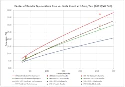
These results were compared to a TEK Center model for predicted heat generation. Figure 3 below represents the comparison of the highest temperature rise of the various cable constructions with respect to the size of the bundle when carrying 1000mA of current across each pair, which closely approximates the conditions of Class 8 power delivery. The model provides a high degree of correlation between the measured and predicted data in this test configuration.
Generally, as a cable’s electrical performance improves, the thermal performance also improves. Specifically, the TEK Center’s testing showed:
- Higher category cables experienced less temperature rise than lower category cables.
- In larger bundles, LANmark-10G2 (Category 6 UTP) performed similarly to LANmark-1000 (Category 6A UTP). This is attributable to the construction of a Category 6A UTP cable, specifically its higher twist rate and increased jacket thickness, both of which are needed to meet internal and external crosstalk requirements.
- The best solution for high PoE deployment is the foil isolated Category 6A product, LANmark-XTP. The XTP cable exhibits significantly less temperature increase with 100W PoE deployment. In a 259 cable bundle, the XTP cable is approximately 18°C (32°F) degrees cooler than the LANmark-350 Category 5e cable. This is a significant difference, and will become even more critical as more devices demand higher levels of power delivery over the network. This reduced temperature rise with the XTP cable reinforces its suitability to high power PoE deployment as it helps to ensure the cable reach is maximized under adverse conditions.
Figure 3: Modeled vs. measured temperature rise of innermost cable in bundle in an open tray
Impacts to Installation Methods
In anticipation of moving beyond the delivery of just IP traffic, the TEK Center has been investigating the performance of cables in various installation scenarios. Open tray represents just one instance of many different installation environments. The TEK Center has tested several possible deployment scenarios, including energizing only a portion of the cable bundle, and enclosing the cables in various types of conduit. Each test scenario represents a distinctly different deployment option and has a varying impact upon the resultant temperature.
Energizing a Portion of the Cable Bundle
To represent a group of power-delivering cables insulated by other cables in a cable tray, the TEK Center built 37-cable bundles of the various categories and surrounded them with 7 groups of identical 37-bundle designs to build large 259-cable bundles. Only the center 37 cables were energized with 1000mA of current to represent a installation with only an approximate 14% PoE deployment. The cables under test exhibited a temperature rise when compared to tests of the same categories in 37-cable bundles in the open tray. The comparative measurements are shown in Table 2. Again, the LANmark-XTP cable exhibited significantly less temperature rise when compared to standard Category 5a constructions.
Table 2: Worst case temperature rise (°C) for the center 37 cable lengths energized with 1000mA in a large bundle of 259 cables
Testing in Conduit
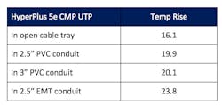
The TEK Center also measured the heat rise of cables placed inside various conduits. In order to approximate a loaded conduit, an 80-cable bundle of HyperPlus 5e was built and energized with 1000mA to measure the impact of conduit installation. The bundle was first built and measured in the open tray for a reference temperature rise. HyperPlus 5e was selected as a worst case study as the smaller diameter allowed for more cables to be installed in the conduit. Larger cables would reduce the number of cables in the bundle and reduce the overall heat generated making the HyperPlus 5e the upper bound of expected heat rise. Table 3 denotes a 4-8°C difference in temperature rise in an open tray versus inside conduit. It is interesting to note that the metallic conduit results in a higher temperature rise instead of acting as a heat sink and helping to disperse heat. This is attributed to the inner non-conductive coating of the conduit acting as an insulating layer preventing heat from dispersing into the ambient environment.
Table 3: Worst case temperature rise (°C) for 80 HyperPlus 5e cable length bundle (1000mA)
Conclusion
As the ecosystem of powered devices continues to grow, power delivery and heating characteristics will soon join other traditional cable performance parameters as a factor in the selection of cabling. Cabling must be able to ensure the delivery of increasing power and data speeds in adverse conditions over its expected lifetime. To maximize the capabilities and efficiencies of tomorrow’s system, the correct cabling infrastructure will need to be implemented.
Selecting a higher grade of cabling will reduce heat generation within the cabling infrastructure, minimize the impact to IP traffic traversing the network and reduce the aging effect that heat can have on insulating materials. Over time, as more devices are connected and powered over the network infrastructure, the selected solution employed in the network will have a growing impact on network performance. Cables with temperature listings of at least 75°C will be better suited to resist the aging impacts of elevated ambient temperatures over time. It is important to think about the expected lifespan of the network infrastructure, and the total lifecycle costs of selecting one option over another. In the vast majority of network IT projects, the cabling cost is negligible relative to the total project costs. Yet it can have a very significant impact on your network’s performance for years to come.
Finally, foil-insulated cables such as the Berk-Tek LANmark-XTP product will provide increased robustness with the best deployment options for PoE due to the minimized thermal gains inherent in its design. Metallic tape on the XTP product allows heat to transfer out of the cable much more efficiently than cable designs without this type of construction. This will allow for maximum ease, performance and flexibility when planning for PoE deployment. The LANmark-XTP product has been specially designed to be Berk-Tek’s best performing product for PoE applications.
