Q: When I prepare my design specifications, I provide a list of transmission requirements and specify that the data cabling system channels meet or exceed those requirements.
I need some help interpreting Draft 10 of the Category 6 standard. I don't see any values for attenuation to crosstalk ratio (ACR), or power-sum ACR. Are ACR and power-sum ACR not included in the standard? If they are, where do I find the permanent link and channel values?
I found tables for Category 6 cable longitudinal conversion loss (LCL) and connecting hardware LCL, but no LCL channel values.
Finally, I find the entire 7.5 propagation delay/delay skew paragraph extremely difficult to use. I see only four values (1, 10, 100, and 250 MHz) for propagation delay or delay skew.
Any light you can shed is most appreciated.
Anthony M. DeShiro, RCDD, Project Engineer
EDvance Technology Design Inc.
Chelmsford, MA
A: In 1997, when TIA first began to actually develop Category 6 cabling, one of their objectives was to create a channel that would support positive power-sum ACR margin up to 200 MHz.
And today, Draft 11 of what will soon be published as ANSI/TIA/EIA-568B.2-1 Transmission Performance Specifications for 4-Pair 100-W Category 6 Cabling, states, "The Category 6 channel transmission requirements specified in this Standard result in a power sum attenuation to crosstalk ratio (PSACR) that is greater than or equal to zero at 200 MHz."
That is pretty much the extent of the discussion about power-sum ACR that will be provided within ANSI/TIA-EIA-568B.2-1. And, there are no performance requirements in any of the TIA cabling standards for ACR.
ANSI/TIA/EIA-568B.2-1 does specify Category 6 transmission requirements for the following:
Insertion loss, including:
- Cable insertion loss
- Connecting hardware insertion loss
- Permanent link and channel insertion loss
NEXT loss, including:
- Pair-to-pair NEXT loss
- Cable pair-to-pair NEXT loss
- Work area, equipment, and patch cord pair-to-pair NEXT loss
- Permanent link and channel pair-to-pair NEXT loss
Power-sum NEXT loss, including:
- Cable power-sum NEXT loss
- Permanent link and channel power-sum NEXT loss
ELFEXT and FEXT loss, including:
- Pair-to-pair ELFEXT
- Cable pair-to-pair ELFEXT
- Connecting hardware pair-to-pair ELFEXT
- Permanent link and channel pair-to-pair ELFEXT
Power-sum ELFEXT, including:
- Cable power-sum ELFEXT
- Permanent link and channel power-sum ELFEXT
Return loss, including:
- Horizontal cable return loss
- Stranded conductor cable return loss
- Connecting hardware return loss
- Work area, equipment, and patch-cord return loss
- Permanent link and channel return loss
Propagation delay, including:
- Cable propagation delay
- Permanent link and channel propagation delay
Propagation delay skew, including:
- Cable propagation delay skew
- Permanent link and channel propagation delay skew
Longitudinal conversion loss (LCL), including:
- Cable LCL
- Connecting hardware LCL
Longitudinal conversion transfer loss (LCTL) for cable and connecting hardware are not currently specified, but are identified as "under study."
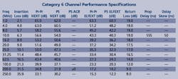
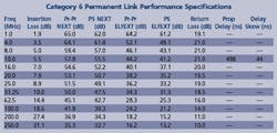
Unless you plan to take up manufacturing cabling components as a cottage industry, you are probably only interested in the permanent link and channel requirements. (See tables, page 16.)
Permanent link and channel LCL are not currently addressed within the standard. The TIA develops standards from the component level up. Cable LCL and connecting hardware LCL were recently introduced into the TIA standards. Hence, we may see permanent link and channel LCL specified in a future revision.
Because propagation delay and delay skew are linear, permanent link and channel testing is only specified at 10 MHz. Specifically, propagation delay for permanent link and channel is in 7.5.2 and delay skew for permanent link and channel is in 7.5.4.
Draft 11 wrinkle
This one will be a problem for designers, installers, and end users. The problem: If you are using minimally compliant Category 6 components to construct a three-connector permanent link, the sum of the NEXT loss contributed by each component can exceed the allowable permanent link NEXT loss limit.
To resolve this mathematical quagmire, a note was added to Draft 11 stating, "NOTE-Permanent link NEXT loss test limits are more stringent than channel NEXT loss limits to ensure that permanent links can be extended into compliant channels using additional cabling components that meet the minimum specifications in this Standard. When a consolidation point is present in the permanent link, the modeling predictions of permanent link NEXT loss performance using worst-case components show margins that can be below the measurement accuracy for the permanent link. NEXT loss performance can be improved by ensuring at least a 5-meter (16.4-foot) distance between the consolidation point and the telecommunications outlet connector. Alternatively, channel testing can be performed with compliant channel cabling components that remain in place." A similar note was also added for PSNEXT loss.
Translation: If you can meet the requirements for the permanent link in the table on page 16, then plug in the user patch cords and test to the less-stringent channel requirements, leaving the cords in place once the testing is complete.
I asked the TR-42.7 Copper Cabling Subcommittee how they intend for installers and end users to manage these cords hanging out of unused outlets. I was told that the group was only addressing ballot comments, not questions from the floor.
So, if you are designing three-connector links and they are not passing, the Category 6 standard offers you a couple of solutions. One solution: do not use three connectors in the link-no consolidation points, or use either home-run UTP cabling or a fiber to the zone solution. Another solution is to plug in the patch cords and run a channel test. This is effectively stealing some of the margin allocated for the addition of the user and equipment cords. Patch-cord manufacturers are going to love this.
If you absolutely must use consolidation points in a Category 6 system, then do not use patch panels with 8-pin modular connectors as the consolidation point hardware. Use Category 6-rated IDC termination, such as 110 or BIX blocks, for the interconnection.
And my last bit of advice for this month: Do not field manufacture/terminate Category 6 patch cords.
Ever wonder why?
If Category 6 cabling is as compatible and intermateable as Category 5 and 5e, then why are we having to buy manufacturer-specific test heads for our new field testers?
Donna Ballast is BICSI's standards representative, and a BICSI registered communications distribution designer (RCDD). Send your questions to Donna via e-mail: [email protected].


