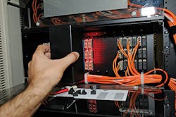
Visual fiber tester technology eases fiber test practices. Here is the story of how it was born.
By Erkan Gunal, Click2See.us
The most practical field test instrument for troubleshooting optical fiber links in the field is the visual fault locator (VFL), also called the visual fault finder (VFF). This article will discuss existing best field practices and technologies in the visual fiber testing category, along with other methods. It also will challenge traditional field practices and advance current technology a step with a new testing method.
A VFL operates in the visible light range. It is used to identify individual optical fibers within a cable by sending a red light down the optical fiber. When used as a troubleshooting tool, the optical fiber strand will glow at the point of a break or separation of optical fibers.
Units that pulse on/off are easier to use when looking for a break. These tools can also be used to detect a damaged optical fiber ferrule. Normally, red laser light should appear as a sharp bright dot in the center of the endface of the white ferrule. If the ferrule is cracked or damaged, the entire ferrule will glow red during this test.
A visual light source also is called optical fiber light-emitting diode (LED) or optical flashlight. It is used to test and troubleshoot continuity of optical fiber strands. By connecting the optical fiber flashlight to one end of an optical fiber strand, then looking into the other end, a technician can determine if there is a break in the strand because if there is such a break, the light will not be visible.
The user should never look at the optical fiber strands until after personally confirming that it is disconnected from potential laser light sources. Laser light sources can cause eye damage.
What is the number one reason for failure for all optical fiber networks? If you said a contaminated fiber-optic connector, you are correct. According to a study conducted by NTT Advanced Technology, and cited frequently, 98 percent of cable installers and 80 percent of network owners reported that contamination had been the root cause of network failures. We are always advised to use industrial-specific fiber-optic cleaning products after each mating of a fiber-optic plug and an adapter or port. A tester's patch cords or VFL's adapter tip can easily carry contamination from one fiber port to another.
Wouldn't it be nice if we could use a VFL with no patch cords or ports at all? An ideal scenario would be a VFL that did not allow a direct contact with the fiber link under test, thereby eliminating the transfer of airborne dust contamination.
Another common problem associated with the VFL is not having an appropriate adapter interface (e.g. SC, LC, ST, FC, MTRJ, MPO) for the given fiber-optic plant. The VFL can test only one fiber port at a time, which is a time-consuming field operation.
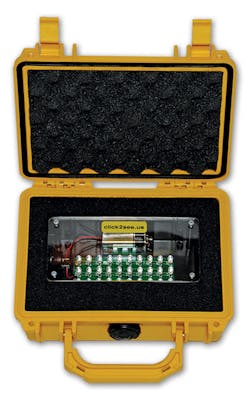
The technology called Rapid Visual Fiber Optic Cable Tester, also known as the visual fiber tester (VFT), aims to improve and simplify visual fiber-optic field testing for technicians with little experience. This patented technology (U.S. Patent Number 8,208,134) is a compact handheld fiber-optic test instrument that can be used to pre-inspect multi-strand fiber-optic cable terminations or splices. It enables technicians to inspect all fiber strands at once based on visual comparison.
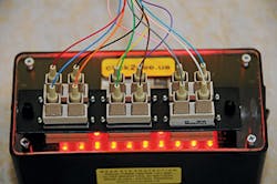
Conventional techniques test only one pair or strand at a time, while this new technology offers instant and rapid field testing of multiple pairs or strands, up to any number, simultaneously, improving productivity and efficiency when compared to test instruments and techniques of today. Because a dust-free test environment is a must, the VFT uses no patch cords at all, so potential contamination is minimized at the core level of a single fiber strand. Because there is no physical connection with the tip of a fiber connector, dust is not carried from one pair to another using a tester's patch cords. This application provides a total non-contact testing method for fiber-optic plants, so the chances of damaging an existing fiber-optic connection are minimal. The electronics inside the tester include no invisible laser components, so the risk of optical eye hazard also is minimized.
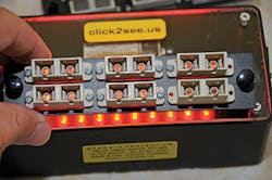
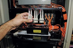
The VFT is a fast, clean and simple compact handheld fiber-optic test solution that enables the simultaneous pre-inspection of all strands of multi-strand fiber-optic cable terminations for defects. It is compatible with any type or brand of fiber-optic adapter panel, coupler, or connector. Its dust-free and non-contact design allows inspection of a group of optical fiber terminations through any existing fiber adapter panel without requiring a direct patch cord connection. No certified technicians, far-end devices or smart remote units are required. The VFT technology has revolutionized rapid visual fault inspection for multi-strand fiber-optic cables-multimode or singlemode-making the process more efficient and less labor-intensive.
When using the VFT, results are observed at the fiber links' far end. Specifically, a bright red dot indicates a good termination, with minimal dB loss. A link with a bright red dot is likely to pass a certification test if the connector tip is cleaned. A link with a dim red dot indicates a poor termination and high dB loss. It will fail a certification test unless the splice or connector is replaced. A link with a dark or black dot indicates a cut fiber. There is no optical continuity, and optical time-domain reflectometer (OTDR) troubleshooting is necessary to locate the break.
VFT's inspiration
The inspiration to develop the VFT came when I was a telecommunications contractor in Los Angeles, CA, implementing the federal E-Rate program for the Los Angeles Unified School District (LAUSD). I had a highly specialized fiber-optic installation crew hired from the local union. My company was bidding an average of 10 to 15 new schools per month. At the E-Rate program, we were pulling new horizontal fiber-optic cables inside each classroom, along with copper workstation cables, installing backbone fiber-optic cables and terminating them in wall- or floor-mounted cabinets located in telecommunications rooms (TRs). While bidding 10 to 15 new projects per month, we also were bringing about the same number of projects to final or substantial completion each month.
With this fast-paced work tempo, our fiber crew had to pass 100 percent of their cable-certification inspections, which were signed-off by the district's consultant inspectors-the facilities technology program management group (FTPMG). The district inspectors were extremely thorough, and their inspections were challenging to pass because the inspections would not tolerate any deficiencies from what was spelled out in the original contract specifications.
My field testing crew was responsible to perform bidirectional OTDR testing on campus fiber-optic backbone runs over 100 feet, as well as performing power-meter tests on all fiber-optic cables along with copper tests on horizontal workstation drops. Our internal pre-test effort was extremely important in order to validate and prepare the site for formal closeout inspection with the district inspectors. The inspectors usually performed a 10-percent spot check based on existing test reports, and required 100-percent retest and reinspection after a certain threshold of failures. Identification, labeling and maintaining as-built records were also as important as the test reports on file.
One of my school projects was behind schedule and I needed to move my core team to another project. I assigned one of my fiber technicians to terminate all fiber strands in the campus. After several weeks of hard work, I came back to check on the project's progress. All the fiber cables were neatly terminated, dressed and labeled. It looked like we were ready to call for inspection. Because of the time-and-labor shortage, we did not perform any pre-test at this school; I called for final inspection and invited the district inspectors to the project site. Sadly, about one-third of the fiber terminations were defective and failed the required power-meter testing. This was both frustrating and embarrassing for my company and for me. The district inspectors walked away, letting us know the project was not yet ready for final sign-off. We had to come back and troubleshoot the failed fiber connections, then call for re-inspection at a later date.
This unfortunate event also served as the moment when the idea for the VFT inspired me. I should have had a tool that enabled me to take a quick snapshot of all the fibers at once, visually recognize which connections were good and which were not, and determine whether or not the site was ready for final inspection. Moreover, such a tool could help me determine whether or not the technician on the job was qualified for the job, before it was too late.
I would be able to prepare a quick punchlist for all dark and high-loss connectors so the troubleshooting crew could focus their attention on those failed fibers. The VFT idea was born by the time I pulled out of that school's parking lot-with a look of disappointment on my face but also with the internal excitement of inventing a test instrument to help me instantly judge what my fiber crew had done over the past several weeks. I would be able to determine the quality of campus-wide fiber terminations without using sophisticated field test instruments, and in doing so I would save a significant amount of time on initial troubleshooting.
Upon arriving home, I began working on a prototype of a VFT in my garage. A week later, I was trying the new instrument in the field and it was working just as I had hoped. I shared the idea with a few of the technicians and inspectors on the jobsite. One of the district's toughest inspectors praised the instrument. Roger Cook, a construction manager with LAUSD's FTPMG, said, "I feel that this is an outstanding tool where not only fiber-trained personnel will benefit, but also novice or, actually, someone with zero experience as well. I think that the real benefit of this tool would be for a large corporation's IT manager, or a telecommunications company that outsources their fiber terminations. With this tool, they can quickly verify, before a technician leaves the site, that the terminations are good-or verify provided test results are accurate.
"Other uses would be inspection, training, or just to verify your own terminations, saving yourself a costly return trip," he continued. "This also would be invaluable for a company to be able to show a customer that a termination is good due to being able to reference with three or more other lights. There is no learning curve to use the tool. Some might say that a fiber test does the same only better, which is true if you know how to use one. But if you don't, then you would not be sure if you are being lied to by the contractor. With the lights, it is undeniable. And as a contractor, rather than a long, drawn-out argument over where the trouble is, you are easily able to show the customer that your fiber is good-and possibly bill for a trip.
"With regards to inspection," Cook concluded, "it will be a great tool that will quickly let you know the skill level of your contractor or if he is trustworthy or not. With inspection, the biggest hurdle for a contractor is to gain the trust of the inspector."
Part of the process
VFT technology is an enhancement to the fiber certification process. It exists in concert with other, established methods of fiber inspection and testing. Following, I describe those methods as well as the tools used to carry them out.
Optical time-domain reflectometer (OTDR)-An OTDR is used to characterize optical power reflected along optical fibers with a graphical signature on a display screen. The OTDR has the capability to measure the length of the optical fiber and characterize the optical power loss between any two points along the optical fiber. This equipment is built with highly sophisticated and sensitive electronic components.
The OTDR, which requires access only to one end of the fiber, sends pulses of light into an optical fiber and measures the strength of the power reflected to the instrument. The OTDR takes thousands of measurements and displays the average of the returned power levels on the screen as a characteristic trace. The trace forms a line with a negative slope from left to right. It is a great troubleshooting tool for localizing or identifying the exact location of a failure in the link.
Optical loss test set-The optical loss test set (OLTS) can include a power meter, cable analyzer or certifying tester. The principle technique is to use an optical transmitter (light source) at one end of the cable, and an optical receiver (power meter) at the cable's other end. This technique is also known as end-to-end attenuation testing. An attenuation tester measures the optical power loss between cable termination points.
Acceptable loss values are established according to the link loss budget for the cable under test. A specific type of optical jumper patch cord is required between the permanent link (the optical cable under test) and the testers (transmitter and/or receiver). A reference value (field calibration) is required prior to testing. If the jumper cables are dirty, the reference value will be higher and the attenuation measurement will not be accurate. Therefore, jumper cables must have the same core size as the optical fiber cable that is being tested. If the jumpers are disconnected or the equipment is turned off after the field calibration process, the reference value is no longer valid and the testers should be recalibrated. Before recalibrating, the testers should be left on for 10 to 15 minutes to let the drivers stabilize. The testers should come to the temperature at which they will be used before calibrating, because driver output can change with temperature. If the testers have been sitting in a hot vehicle in the summer, or overnight during the winter, it may take an hour or more for them to reach the temperature at which they will be used.
The testers should be recalibrated after any event that can affect the amount of light being injected into the optical fiber, including disconnecting, reconnecting, changing the jumper cables, replacing batteries, and other actions. Good batteries also can be important for accurate test results. As batteries get weaker the voltage may drop, and some testers will begin to give erratic results before the testers stop operating completely. If the testers use disposable batteries, it is unlikely anyone will keep track of when the batteries were replaced. To achieve the most-accurate loss measurements during calibration and testing, a multimode launch cord is required and should be wrapped five times (non-overlapping) around the mandrel before calibration. The diameter of the mandrel is also an important factor. If a mandrel is not used during testing, the consistency of the test results will be suspect. Some new-generation testers do not require the use of mandrels. Be sure to find out if your OLTS does or does not require the use of a mandrel.
Strand identifier-A clamp-on unit inserts a macrobend into the optical-fiber cable and thereby is able to detect the light escaping from the optical fiber. This device is used to detect the presence of light, as well as transmit and receive direction on singlemode and multimode optical-fiber cable.
Fiber-optic microscope-A handheld or desktop microscope with different magnifying areas, such as 250x, 300x, or 400x, is a well-known optical instrument used to visually check the surface of fiber-optic core and cladding on terminated and polished connector ferrules. The fiber-optic microscope also comes with a fixed or interchangeable adapter interface where the fiber connector plugs in.
Why do we need to clean?
Cleanliness is the biggest concern and most-overlooked factor during fiber troubleshooting. Every optical fiber test practice dwells on cleanliness, and for good reason. Poor cleanliness practices are the single greatest cause of problems in optical fiber testing and operation. Cleaning optical fiber connectors requires lint-free paper or 99-percent reagent isopropyl. Alcohol available at a pharmacy may look and smell the same, and probably even has the word "isopropyl" on the label, but often it is only 70 percent pure, with plenty of room for impurities. The wipes must be lint-free and made for this type of work. If using canned air to blow adapters clean, it should be made specifically for this purpose. Canned air that is used to clean keyboards and is available at office-supply stores can have many impurities.
To clean an optical fiber connector, the technician should wipe the connector ferrule with an alcohol-dampened wipe. The alcohol helps dissolve dirt that may be on the ferrule. After cleaning with the moist wipe, the ferrule must be polished with a clean, dry wipe to remove the alcohol and dissolved dirt. If the ferrule is allowed to air dry without wiping, the dirt in the alcohol is redeposited on the ferrule.
After cleaning, the technician should put the dust cap on the connector immediately. This prevents damage to the ferrule and helps reduce contamination.
There is dust in the air all the time, and the cleaning process may create a slight electrostatic charge on the connector that can attract dust from the air. A capped connector should also be cleaned before it is plugged in. The plastic in some caps can deposit contamination on a ferrule. The ferrule's endface should never be touched during testing; even "clean" fingers will leave an oily coating. Dust covers should be kept on all adapters until immediately before a connector is to be inserted. If a technician receives a failing test result for one link, the fiber-optic connector should not be plugged into another adapter for comparison without first being cleaned. Contamination can easily spread from one adapter port
to another.
It is especially important to keep the ports in preterminated cassettes clean. Unlike traditional optical-fiber cabinets that allow a technician to unplug a connector on the inside for cleaning, preterminated cassettes are generally factory-sealed, making ports difficult to clean if they are contaminated. This is also true of MPO ribbon connectors on the backs of cassettes. They are difficult to clean once they are contaminated. Some suppliers now offer an advancing-tape cleaner that can be inserted into an adapter or female connector. These cleaners are often but not always successful.
In conclusion, visual fiber tester (VFT) technology provides a practical and cleaner technique for visual continuity and attenuation testing of multiple-strand optical-fiber cables by trained as well as non-technical persons, without the need for fixed adaptive interfaces, couplers, adapters or specific patch cords. It is compatible with a wide range of vendors' products, and offers a dust-free testing experience by using existing, standardized fiber-optic adapter panels, couplers, and connectors.
The VFT does not require routine maintenance, calibration, extensive training, or certification for proper use. It will be beneficial for use in the data center environment, where high-density MPO/ribbon connectivity is being deployed. Installers can quickly and easily verify preconnectorized high-density cabling trunks before and after installation. The first time an installer identifies an optical fiber continuity problem with the VFT, it will take less time than other troubleshooting methods to act and begin resolving the issue.
Erkan Gunal, BSEE, RCDD, NTS, NICET-III, STS, is a product designer and inventor, and president of Click2see.us, LLC (www.click2see.us). He holds patents on three technologies, including U.S. Patent Number 8,208,134.
