In mid-1999, the Institute of Electrical and Electronics Engineers (IEEE) formed a task force to standardize the approach for passing power over Ethernet (PoE) The concept is simple, but its implications are enormous.
Using the standard Ethernet network infrastructure and cabling, electrical power is distributed to power LAN-connected devices, such as IP phones, wireless LAN access points, and network cameras. With PoE, powered devices (PDs) become easier to deploy and more reliable, enabling companies to save potentially tens of thousands of dollars on their communications infrastructure.
Traditionally, LAN installations have required operating power to be delivered separately to each remote LAN device. Given the increasing quantity of LAN devices and the increasing need to support critical applications, installing a dedicated uninterruptible power supply (UPS) for each device is prohibitively expensive. Furthermore, many of these specialized devices have to be installed in specific locations for proper operation. For instance, to achieve effective radio coverage and reception, wireless LAN access points are mounted above the ceiling plates where it is rare to find an AC outlet. PoE, however, affords point-to-multipoint power distribution architecture, parallel to the data, while using the existing cabling network.
The IEEE 802.3af standard, which was ratified in July, specifies the way to build Ethernet power sourcing equipment (PSE) and PDs, and how to deliver 48 V of DC power to networked devices while maintaining data integrity.
PoE architecture
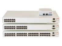
The standard defines two alternatives for delivering the power—end-span and midspan. End-span refers to an Ethernet switch with embedded PoE technology. Midspan is an application-specific patch panel-like device, with multiple channels (typically, 6 to 24), that is placed between any legacy Ethernet switch and the PD. 10/100Base-T (Ethernet and Fast Ethernet) use two pairs of a typical four-pair Category 5, 5e, or 6 cable—one pair for transmission and a second for receiving data. The other two pairs are free.
End-span PoE devices typically use the twisted pairs that are used for transmission and reception of 10/100Base-T, while midspan devices use the two spare pairs in a 10/100Base-T setup.
In both scenarios, the power is transferred in a common mode over four conductors, between the two pairs. The PD should be able to present a valid PoE signature and accept power from either pair.
Nevertheless, PoE technology maintains Ethernet data integrity and avoids any potential damage to existing legacy, locally-powered Ethernet devices and cabling infrastructure. Practically, PoE does not require any modification to the previously installed cabling plant, including Category 3, 5, 5e, or 6; horizontal and patch cables; patch panels; outlets; and connecting hardware.
PoE safely allows mixing legacy Ethernet devices and new LAN-powered devices. A "detection" mechanism, embedded in each power-feeding port, is responsible for unambiguous identification of the attached terminal. Only terminals that present an authenticated PoE signature will receive power. This assures installers and users that they are automatically protected against wiring mistakes and can freely mix legacy Ethernet and PoE devices on the same network.
Wiring and power
Wiring presents the biggest challenge to the 802.3af networks. The wiring and patch panel connectors influence the amount of current that can be carried and how the power can be inserted onto the line.
The Ethernet-delivered power voltage is nominally 48 V DC, but the standard allows a range of 44 to 56 V DC. The current delivered to each node is limited to 350 mA continuous, and is carried on two wire pairs to comply with safety standards and the physical limitations of the existing cabling. Hence, the total amount of continuous power that can be delivered to each node, taking into account the worst-case power loss over a 100-meter cable run, is 12.95 W. IP phone sets and wireless LAN access points, for example, typically consume 3.5 to 10 W; that amount of wattage is sufficient to charge a laptop battery while the access point is on standby.
Deciding between end-spans and midspans is a challenge contingent upon the cabling transmission budget, which dictates how many transition points, total cable length, number of components, total amount of crosstalk and amount of attenuation are allowed between the switch and the PD's physical layer transceivers. A midspan can be added into a channel with the interconnection configuration. Or, it can replace the equipment-representing patch panel in a channel with the crossconnect configuration.
The Category 5 transmission budget is short of allowing midspan units to include line transformers between the input and the output of each channel, resulting in a direct connection of the two Ethernet data-transmission pairs from input to output. That means that midspans are applicable only to 10/100Base-T communication over Category 5 and above.
To address four-pair cabling environments and gigabit Ethernet, end-spans use two transmission pairs to deliver power in what is called "phantom feeding." Because Ethernet data is transferred in differential mode, the power is "phantom"-fed between the two wire pairs in a common mode, allowing data and power to coexist while eliminating mutual interferences.
The power and the loads are actually connected between the receive and transmit line transformer's secondary coil center taps. Since midspans are using wires 4-5 and 7-8 (the unused wires), and end-spans are using wires 1-2 and 3-6 (the transmission wires) for powering, the PD should be able to present a valid PoE signature and accept powering from either pair's sets.
Amir Lehr is vice president of business development and strategic planning for PowerDsine (www.powerdsine.com). He is a voting member of the IEEE 802.3 committee.

