Wireless allows increased productivity by providing communications anywhere anytime.
Jim Romlein, MIS Labs
To meet your clients` needs in their mobile environment, you can install a wireless voice communications system. First, you must decide how many remote cell units are needed by determining the number of users and service requirements of the system. These remote cell units are like tiny cell transmitter/receiver stations that communicate with wireless telephones. After the remote cell units are mounted, you map the coverage area--minimum and maximum traffic fringe--for each remote cell unit. The final installation steps include repositioning remote cell units and documenting their location.
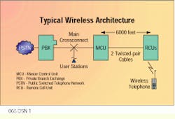
To understand the architecture of a generic wireless system, consider a voice pocket communications system that operates in the 902- to 928-megahertz band, which is available for non-licensed use. In a typical wireless architecture, the private branch exchange is terminated on the main crossconnect and extends over horizontal wiring to the user stations. The master control unit, which is the station-side interface to the private branch exchange, converts the analog signal from the private branch exchange to digital technology. The master control unit is mounted at the main crossconnect and is connected to a number of remote cell units that, in turn, are connected to the information outlets. Before placing the remote cell units, you need to determine how many are needed and their general deployment scheme.
How many remote cell units?
Several proprietary implementations support multiple simultaneous users from a single remote cell unit. The rule in general, however, is to limit four simultaneous users to one remote cell unit.
To develop a deployment strategy, first determine the coverage area requirements. The number of simultaneous users in an area will vary by user group. In a medical environment, doctors, nurses, administrators, maintenance personnel and, from time to time, guests, will use the system of wireless telephones.
A survey reveals that doctors use a wireless telephone for incoming calls anywhere in the complex, but they make most of their outgoing calls from the break room or dining-room area. The same is true for nurses, administrators and maintenance personnel. From this kind of information, you can determine that the system needs to support six simultaneous calls from the break room and the dining room, two simultaneous calls from the wards and the administrative area, and one call from maintenance areas. The coverage survey and the resulting remote cell unit location map are normally provided by the design engineer.
Grade of service, a metric standard used in telephony, can help determine the number of users in a given area who can be served by a specific number of voice circuits. Using statistical traffic theory, you can predict service requirements.
In a sample model system, for example, a single remote cell unit without overlapping coverage can support 0.87 Erlang. (An Erlang is a unit of measure used in traffic studies.) An average business user will generate 0.15 Erlang of telephone traffic. If you divide the 0.87 Erlang available by 0.15 Erlang per user, you will find that one remote cell unit can support six primary wireless telephone users.
If you apply this statistical model for deploying remote cell units to the medical scenario, you can determine that the remote cell units have to support six simultaneous users in the break room and cafeteria. Add to that the requirement for traffic transitioning between microcells, and you find that you will need two remote cell units to cover these areas.
The placement of remote cell units can be the make-or-break part of a wireless installation. When you plan the horizontal wiring, it is a good idea to add several alternate locations for remote cell units. Because buildings differ in materials and layout, you should analyze the floor plan and transmission coverage requirements. This analysis should include an inventory of construction materials and architectural features that may affect transmission; for example, concrete walls and metal air ducts.
Visualize coverage area
Each remote cell unit functions as a radiating antenna, providing spherical coverage to an area 300 feet in diameter. The optimum radiation pattern is along a horizontal line for a distance of 150 feet of clear space. A smaller vertical wave pattern also results. When planning the placement of the remote cell units, assume a concrete block wall and a concrete floor will decrease your coverage area by 75 and 90 feet, respectively. A metal air duct will totally block the signal. Visualize the coverage area as an upright cylinder bounded on the vertical axis by building floors.
Typical coverage of a single remote cell unit in an office environment is 8000 to 12,000 square feet. In such open areas as warehouses and cafeterias, coverage can approach 50,000 square feet. However, there is no sure way to know the exact range of a remote cell unit without testing it.
As a rule, you will need several remote cell units to cover a facility, with overlap to ensure total coverage and a smooth hand-off as the user moves from microcell to microcell. The two main factors that determine the overlap area are the number of users passing through the area for hand-off and stationary users.
System acceptance test
Remote cell units are small and lightweight, so they can be attached to acoustical ceiling tiles, support grids and raised ceilings. To provide maximum coverage, mount the remote cell units at high points. Install the horizontal cable that will serve the remote cell unit with at least 50 feet of slack coiled at the end. Provide this slack even if you exceed the 90-meter horizontal maximum distance allowed by the American National Standards Institute/Telecommunications Industry Association/Electronic Industries Association standard 568A. After you have placed the wireless horizontal cabling, do not close the ceiling until you do a system acceptance test.
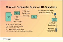
Wireless communications, as defined in ANSI/EIA/TIA-569 and ANSI/TIA/EIA-568A, extends the horizontal structured cabling system standard by 150 feet. For our model system, the manufacturer`s specifications list a 6000-foot link from the master control unit to the remote cell unit. Subtracting 280 feet (90 meters) from the horizontal channel, you are left with a 5720-foot backbone or interbuilding link. This distance is very similar to the backbone distance supported by the typical private branch exchange.
In wireless communications, there is an important dimension to the installation process that you do not have in a hard-wired environment--the system acceptance test. In a hard-wired installation, you use a cable tester to verify the link you have installed and assure the owner that materials and workmanship meet standards. This is not the case in the wireless world. Unless you place remote cell units very short distances apart, you cannot be assured you will have the coverage you need to make the system operate seamlessly. You will need to perform an additional test procedure beyond installed cable verification.
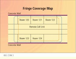
The first step in this system acceptance procedure is to map each remote cell unit`s coverage in turn. With only the remote cell unit that you are mapping connected, walk around with a wireless telephone to find the border of its serving area. Note the exact spot where the signal is lost when you take one more step away from the remote cell unit. Draw this border, known as the minimum traffic fringe, on your floor plan with a colored pencil.
With the same remote cell unit connected, place three stationary users--the maximum number of users for your system minus one--within the traffic area. Again map the fringe and mark this area with a different colored pencil. This is the maximum traffic fringe. You will see that this maximum traffic fringe is considerably smaller than the minimum traffic fringe area.
Repeat this procedure for each remote cell unit in the system. You are now ready to begin the system acceptance test.
Connect and power up every remote cell unit in the system, checking out the high-use areas first. Start with the base number of fixed users online in the coverage areas. In the medical example, for instance, you would have six people connected in the break room. Then have a seventh user go online outside the break area, move into the break area, walk around the perimeter of the serving area mapped for each of the remote cell units and finally move out of the break area.
As you move around the coverage area, make sure you have a good signal level. For example, have the sender play music in the background; that will ensure you have a steady (although only one-way) signal with which to work. On your floor plan, draw a line around any weak zones where the signal is not clear. Also note any dead zones where you lose the signal completely. (Red is a good color to use to identify these areas.)
The coverage map reflects the actual coverage you can get from each remote cell unit in a particular building. You now have a tool that lets you accurately predict coverage-area fringes.
After you have completed the system check for the entire building, evaluate your floor plan. You have three basic options for fixing such coverage-area problems as dead zones or coverage fades: Move the remote cell units, add more remote cell units or both. (This is when you may need that 50 feet of slack at each remote cell unit.)
Use your coverage map to reposition existing remote cell units so the coverage lines meet the system requirements. Make sure to re-test after adjusting the remote cell units.
Troubleshooting the system is straightforward. If you have a problem on one of the wireless telephones, first check out the analog voice circuit. Do this by lifting the link to the master control unit and checking out the hard-wired voice station. Ensure you can dial, talk and ring on the wireless telephone. Then move a known operational wireless port onto the block. If the wireless telephone works, you have something wrong in either the cabling from the master control unit to the remote cell unit, the wireless telephone, the remote cell unit or the master control unit channel card.
A data system is similar in architecture and deployment to the voice pocket communications system described. However, with a data system, you can usually run an application on a personal computer that will help you accomplish the throughput.
While developing horizontal cable-run requirements, you should ask if the building owner wants to wire for a data wireless system at the same time you are wiring for the voice system. It will be more cost-effective to wire for both at the same time. Also ask about adding horizontal cabling for access security. This is the minimum number of additional horizontal cables you should plan to meet your customer`s future needs.
On your as-built drawings, include the remote cell unit coverage fringes and any unused horizontal cabling for future use. Make sure to mark on the drawings where equipment is located in the ceiling.
In a typical wireless architecture, the master control unit is mounted at the main crossconnect and then connected to the remote cell units. These remote cell units can be 6000 feet away from the master control unit and are connected to it by two Category 3 or 5 twisted-pair cables. Wireless telephones communicate with the remote cell units.
Wireless communications as defined in ANSI/EIA/TIA-569 and ANSI/TIA/EIA-568A extend the horizontal structured cabling standard by 150 feet.
Minimum coverage fringe (blue) and maximum coverage fringe (orange) areas indicate where signal is lost from the remote control unit.
Jim Romlein is president at MIS Labs, Watertown, WI.


